Collection of amana ptac wiring diagram. Also a vertical clearance of 60 should be maintained between units installed.

D7c Diagram Ptac Wiring Ge Zr880851 Wiring Library
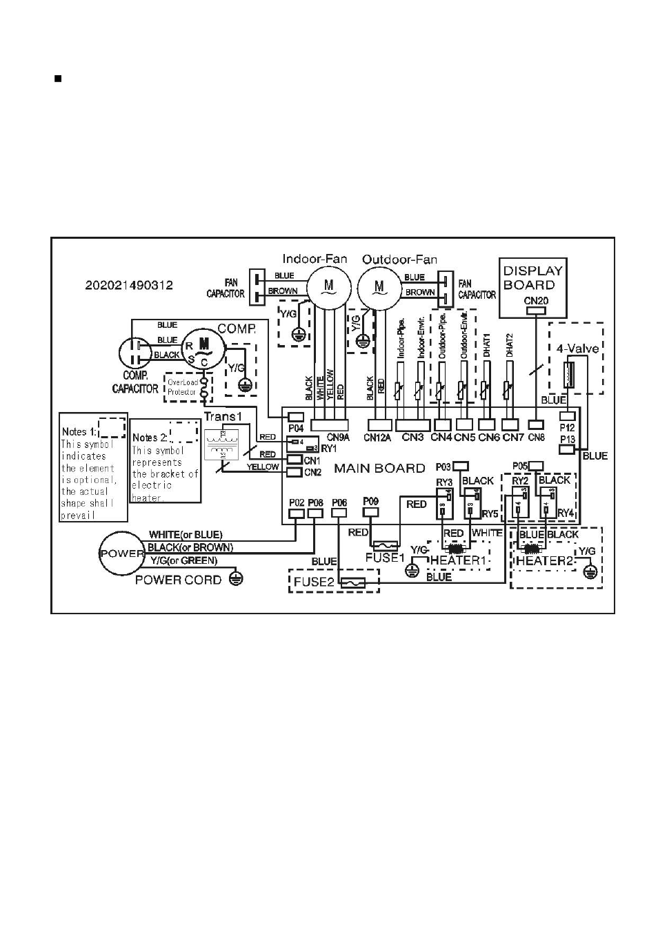
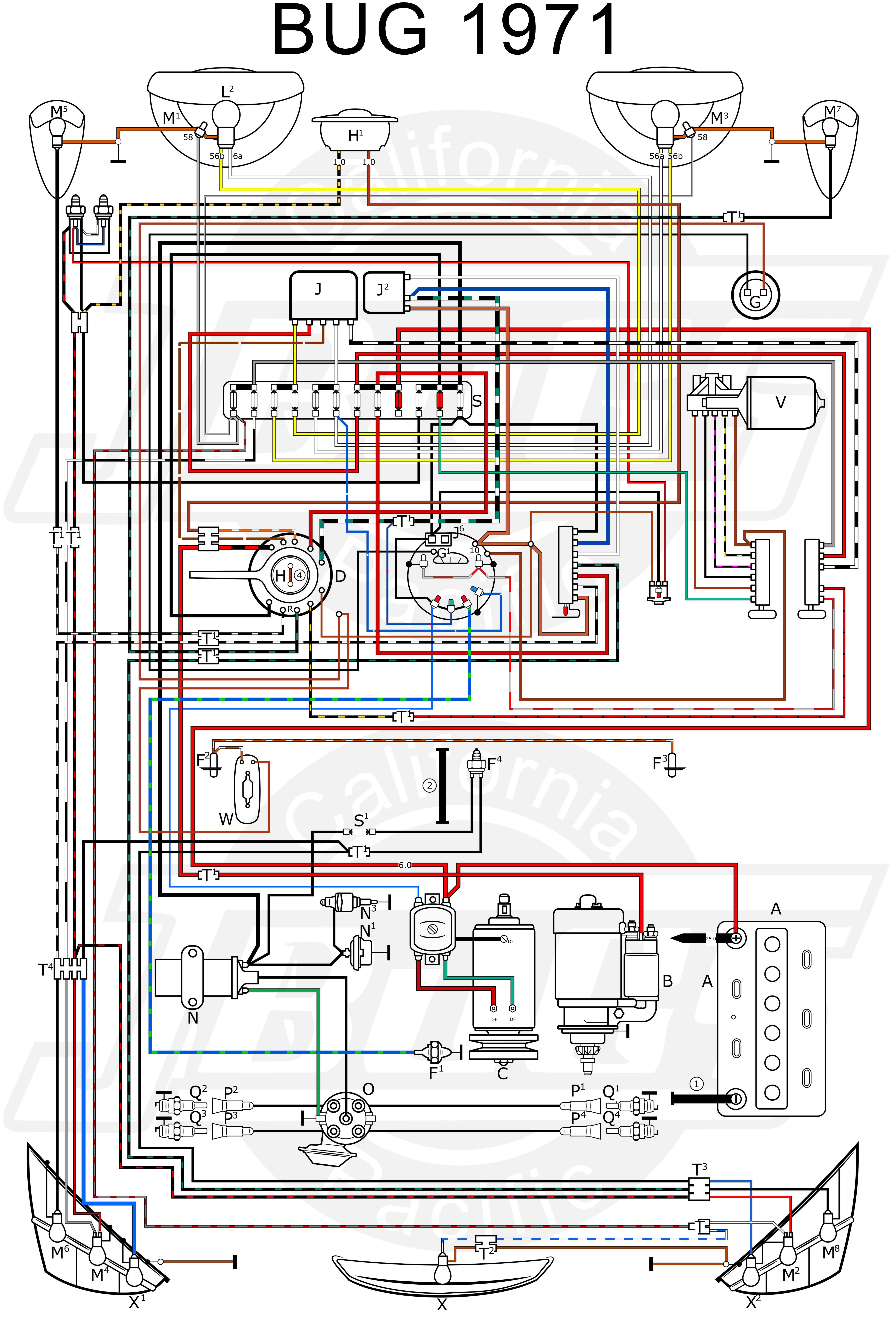
Ptac wiring diagram. Islandaire designs and manufactures a vast selection of thru the wall packaged terminal air conditioners and heat pumps ptac pthp. This information might be about you your preferences or your device and is mostly used to make the site work as you expect it to. Ptac installation recommendations ptac units should be installed no closer than 12 apart when two units are side by side. It shows the parts of the circuit as streamlined forms and the power as well as signal links between the devices. When you visit any website it may store or retrieve information on your browser mostly in the form of cookies. Amana ptac wiring diagram architectural electrical wiring representations reveal the approximate places and interconnections of receptacles illumination and also permanent electrical solutions in a building.
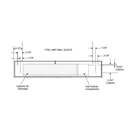
If three or more ptac units are to operate next to one another allow a minimum of 36 between units. How to wire an air conditioner for control 5 wires the diagram below includes the typical control wiring for a conventional central air conditioning systemfurthermore it includes a thermostat a condenser and an air handler with a heat source. The amana ptac pth153g50axxx digismart heat pump 15000 btu 230v 5kw 30a r410a ptac unit is a state of the art design that had both you and your guests needs in mind. Interconnecting cord routes may be shown around where particular receptacles or fixtures need to get on a common circuit. Moreover the heat source for a basic ac system can include heat strips for electric heat or even a hot water coil inside the. In the interior of the room the unit should be.
With amanas one of a kind digismart technology this ptac unit will save you up to 35 in ptac energy costs. Page 64 1400 1250 1200 1000 high high valve alternate alternate outdoor indoor motor motor wiring wiring ptac outdoor motor speed selection high speed low speed model starts with vstm tap vstm tap black wire red wire dry093g00 to 35 1350 1170 dry094g00 to 35. These models can be used for direct replacements or for new construction projects in industries including hotel healthcare schoolsuniversities and modular designs. A wiring diagram is a streamlined traditional pictorial depiction of an electric circuit. Digits 1 2packaged terminal air conditioner digit 3product type e air conditioner with auxiliary heat h heat pump digit 4development sequence e fifth development series digit 5 6 7unit cooling capacity 070 7000 btu 090 9000 btu 120 12000 btu 150 15000 btu.
