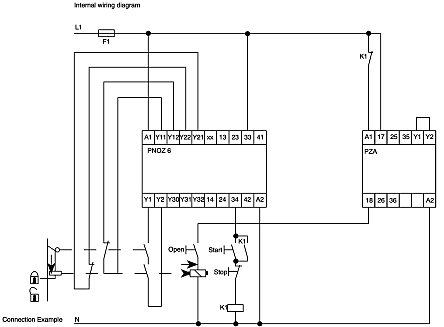
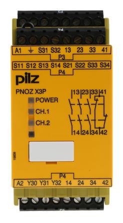
Pnoz x3p nsg d 2 161 2009 09 terminal configuration klemmenbelegungu b 24 vacdc ub 24 240 vacdc installation montagepnozxthe safety relay should be installed in a control cabinet with a protec tion type of at least ip54. Discuss pilz pnoz x3 trying to unerstand in the industrial electrician have the internal wiring diagram i am sure you can google such a diagram.
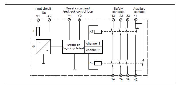
Wiring Diagram For Pilz Safety Relay Diagram Base Website
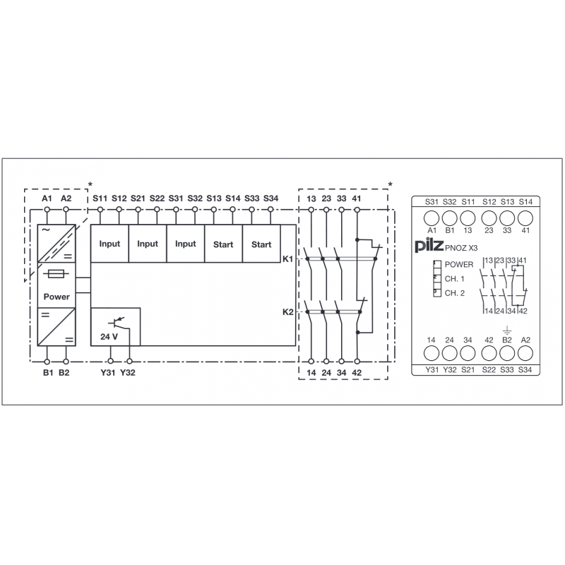
Pnoz x3 wiring diagram. Output 41 42 is an auxiliary contact eg. 1 no 1 nc. Ensure the unit is mounted securely. Pilz pnoz x3 safety relay wiring diagram. Use the notch on the rear of the unit to attach it to a din rail. For display auxiliary contact 41 42 should not be used for safety circuits.
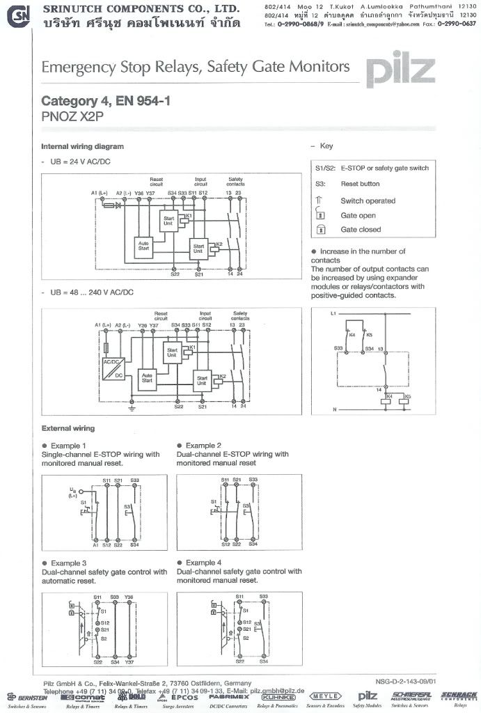
Pnoz x3 internal wiring diagram a1 a2 s13s14 s12 s21 s34 41 42 s11 s22 s31 s32 13 33 14 34 k1 k2 23 24 y32 y31 ch2 start ch1 unit s33 ac dc b1 b2 ub reset circuit input circuit safety contacts auxiliary contact input circuit external wiring example 1 single channel e stop wiring with automatic reset. For display auxiliary contact 41 42 should not be used for safety circuits. Pilz pnoz x3 safety relay wiring diagram safety relays from the pnoz x product range for safe monitoring of e stop inputs. Pnoz x3 operating manual pnoz x3 20547 en 10 11 wiring please note information given in the technical details 16 must be followed outputs 13 14 23 24 33 34 are safety contacts. Pnoz x3 operating manual pnoz x3 20547 en 08 10 wiring please note information given in the technical details 15 must be followed outputs 13 14 23 24 33 34 are safety contacts. 30092018 30092018 3 comments on pilz pnoz x3 safety relay wiring diagram.
Safety relays are usually adaptable to provide coverage for differering. S11 s31 s13 s12 s32 s14 s21 s22 s1 example 2 single channel e stop wiring with. Output 41 42 is an auxiliary contact eg.

