Marantz pm8000 service manual 29 pages marantz pm7000 pm8000 integrated amplifier service manual. 6 111904 clarified power wiring in section 243 and figure 2 1 7 31605 added list of required test equipment in section 211 8 52405 corrected text description for unswitched 3 4 sect 2410 9 62205 added note to section 2413 for dme on aux and logic switching 10 71405 added info on pa jumper j4 to section 2412.
8702 50 Mdr 8000 User Manual Mdr 8000 Radio Family Users
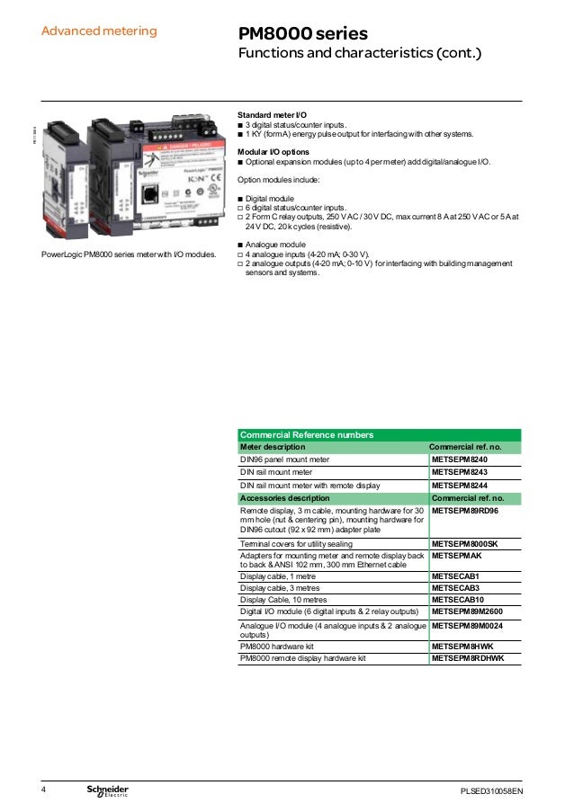
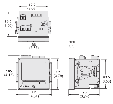
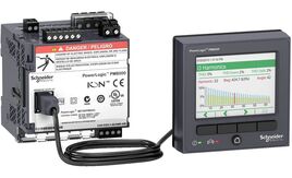
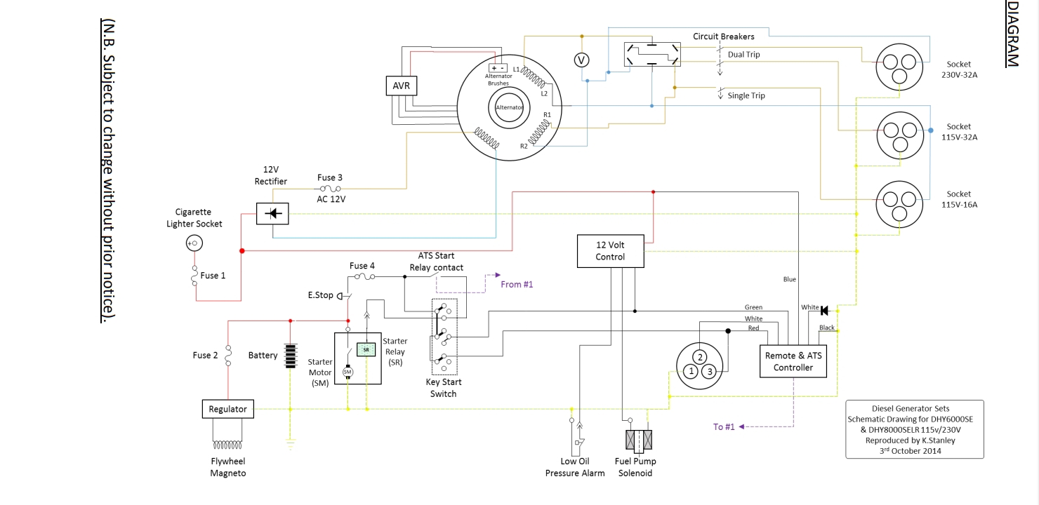
Pm 8000 wiring diagram. Danger hazard of electric shock explosion or arc flash apply appropriate personal protective equipment ppe and follow safe electrical work practices. Danger hazard of electric shock explosion or arc flash apply appropriate personal protective equipment ppe and follow safe electrical work practices. See nfpa 70e in the usa csa z462 or applicable local standards. Pm 8000 wiring diagram wiring diagram is a simplified all right pictorial representation of an electrical circuit. Pm8000 series user manual powerlogic pm8000 series. Installation sheet for powerlogic pm8210 pm8240 pm8280 pm82403 pm82404 power and energy meters describes mounting wiring connecting and verifying operation of the meter.
It shows the components of the circuit as simplified shapes and the faculty and signal associates in the middle of the devices. For example in the united states see nfpa 70e. See nfpa 70e in the usa csa z462 or applicable local standards. Schematic diagram and parts location parts side 21. Wiring diagrams powerlogic series 800 power meter 63230 500 224a1 chapter 4wiring 62006 wiring diagrams danger hazard of electric shock burn or arc flash apply appropriate personal protective equipment ppe and follow safe electrical work practices. Installation wiring testing and service must be performed in accordance with all local and national electrical codes.
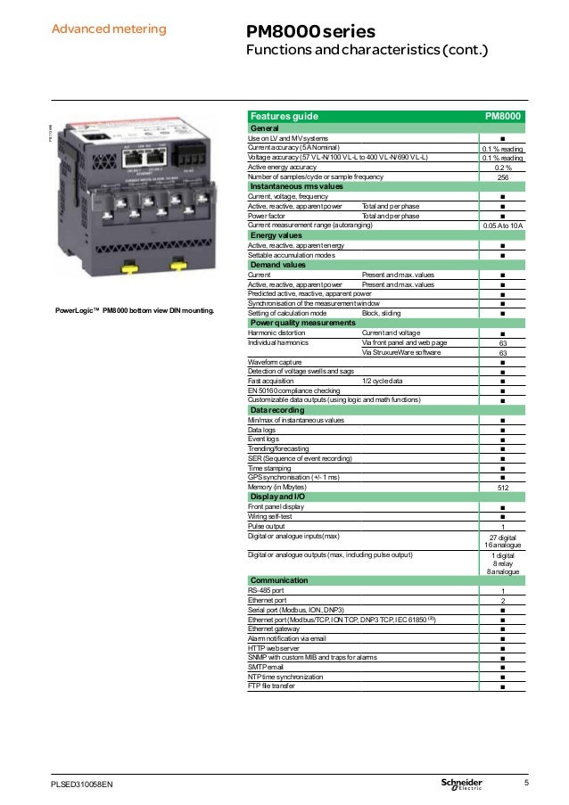
Idling current and dc offset voltage alignment. Exploded view and parts list. The maximum voltage allowed for direct connection may be lower than the manufacturer. You can connect the meters voltage inputs directly to the phase voltage lines of the power system if the power systems line to line or line to neutral voltages do not exceed the meters direct connect maximum voltage limits. Installation wiring testing and service must be performed in accordance with all local and national electrical codes. Wiring self test b pulse output 1 digital or analog inputsmax 27 digital 16 analog digital or analog outputs max including pulse output 1 digital 8 relay 8 analog communication rs 485 port 1 ethernet port 2 serial port modbus ion dnp3 b ethernet port modbustcp ion tcp dnp3 tcp dhcp dns ipv4 ipv6 iec 61850 b ethernet gateway b.


