To wire multiple. All work carried out should comply with all applicable wiring regulations.

Veti Plug Wiring Diagram Electrical Socket Wiring Diagram Two
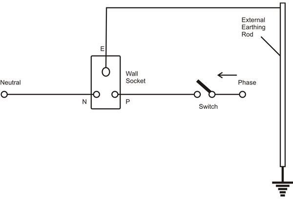
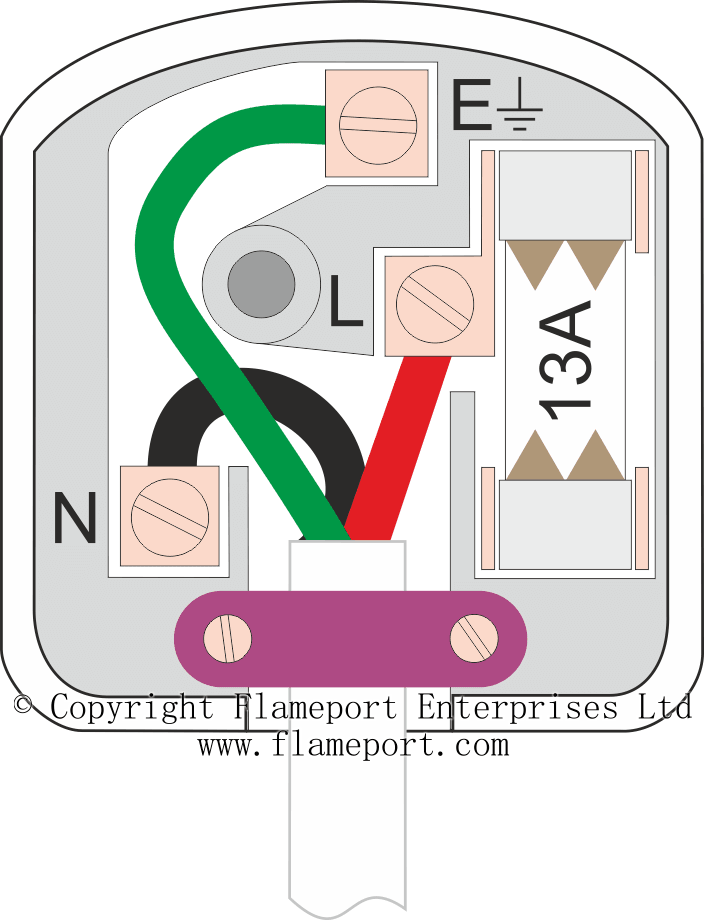
Plug socket wiring diagram. If in any doubt on how to proceed consult a qualified electrician. The threaded socket is the neutral. How to wire an electrical outlet wiring diagram wiring an electrical outlet receptacle is quite an easy job. So hopefully you have now been able to change your plug socket wiring successfully. Double plug socket wiring diagram single plug socket wiring diagram. The images below show the common wiring guide for trailer plugs adapters sockets.
The color key is a breakdown of the wires found in each of their respective systems. The long slot on the left is the neutral contact and the short slot is the hot contact. A grounded contact at the bottom center is crescent shaped. With a combination of visual indicators and beeps that correspond to any faults if any you have made. This is a standard 15 amp 120 volt wall receptacle outlet wiring diagram. When we refer to the socket we are talking about the side of the vehicle where we make the connection while the plug is the trailer side.
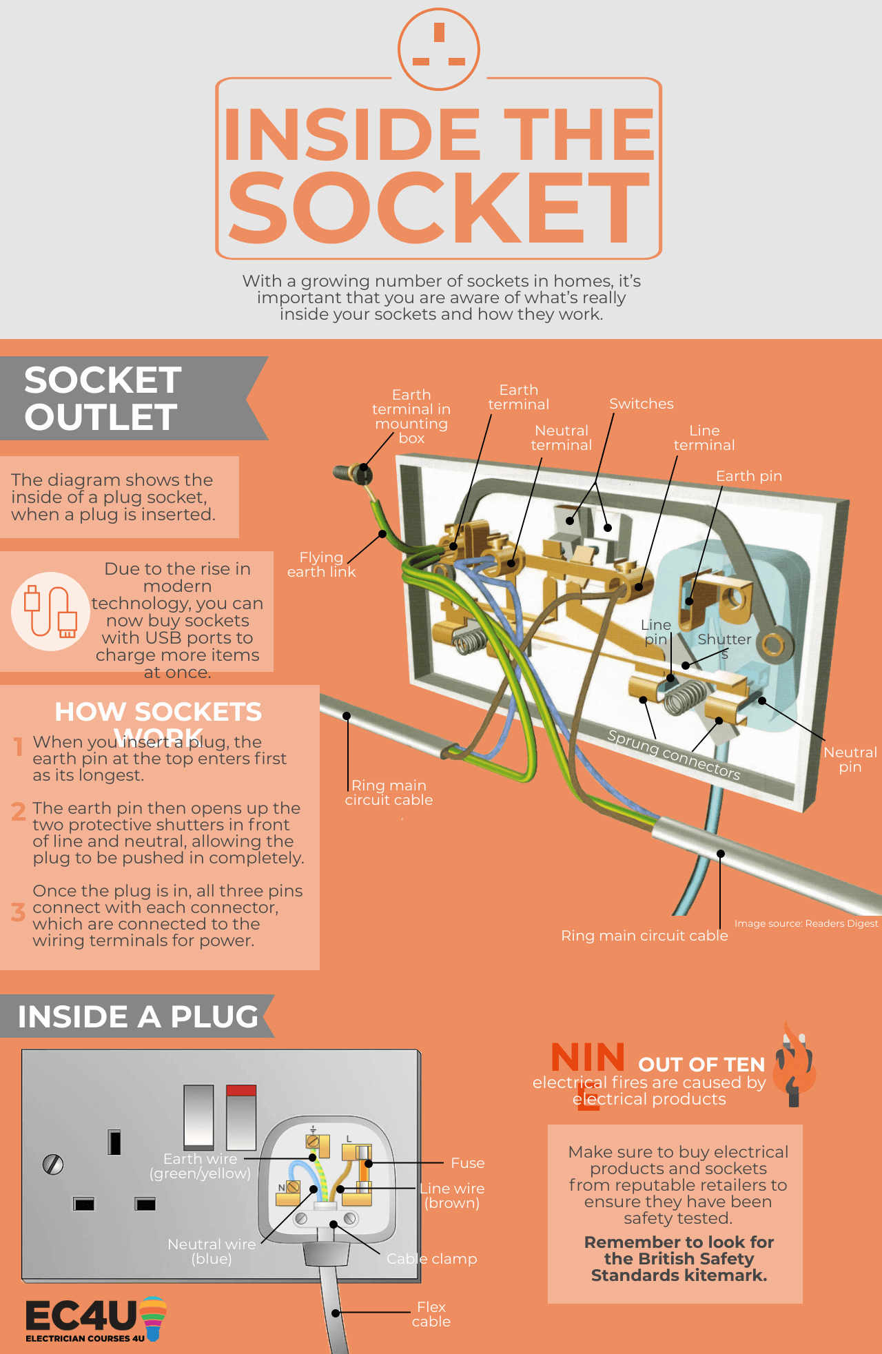
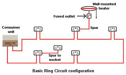
Changing a socket and adding a new one to a circuit are two of the few electrical tasks a diyer can legally do so take a look at its key components with this detailed diagram of the inner working of the humble electrical socket. When making connections you must distinguish between the use of plugs and sockets. Dont use this receptacle when no ground wire is available. Incorrect installation will invalidate your guarantee. If you are fixing more than one outlet the wiring can be done in parallel or in series. Four pin trailer wiring install wiring diagram info.
When connecting an electrical wire to a screw terminal always wrap the wire clockwise around the screw. Buy a polarized plug from home depot right now. No bare wire should be exposed. Illustrations shown represent rear views of connectors. The socket receptacles are usually marked with signs to indicate the position that each wire should go. In electric by magnus sellén 9 august.
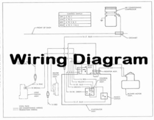
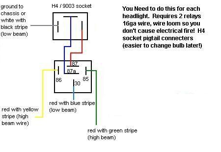
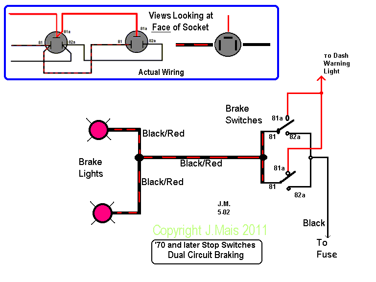
This is a polarized device. So when the switch is off all hot parts of the lamp are well protected. A wiring diagram is a streamlined conventional pictorial representation of an electrical circuit. To double check you have wired it correctly you can purchase a socket tester to verify that you have made your connections correctly. Collection of headlight socket wiring diagram. When wrapped correctly in a clockwise direction the wire will be pulled tighter as you tighten the screw.
And when the switch is on only the tab at the bottom of the socket is hot but if the wiring is reversed and the power goes to the threaded socket the threaded socket is always hot whether the switch is on or off. These secure live earth and neutral within their terminals. It reveals the parts of the circuit as streamlined shapes and the power and signal links between the tools. The photos are what the adapters look like when removed from their housings. Read the instructions carefully before commencing installation.
