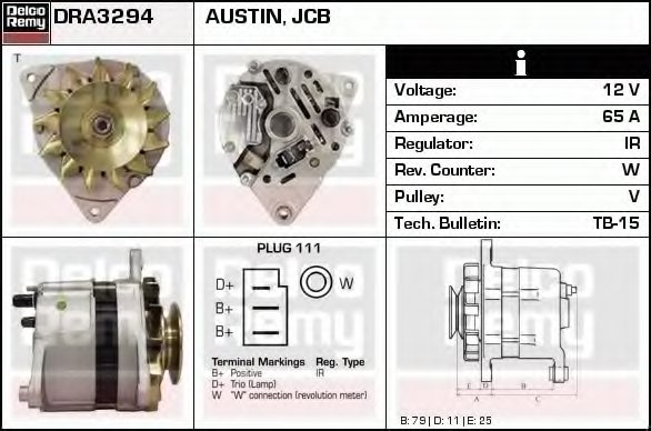
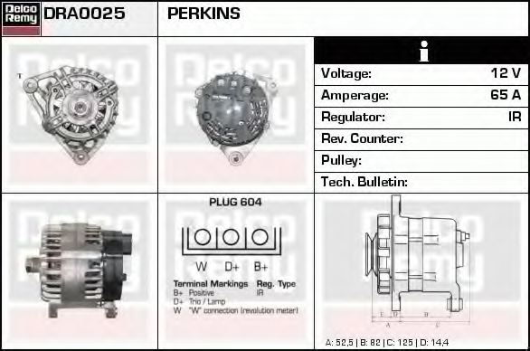
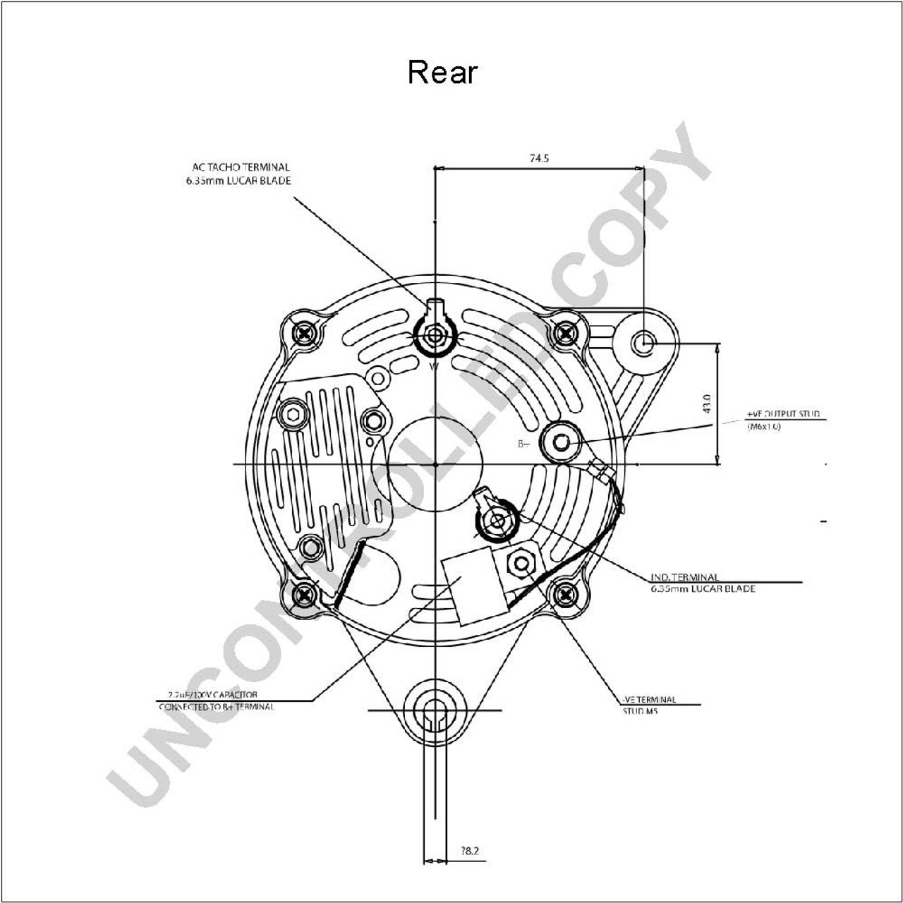
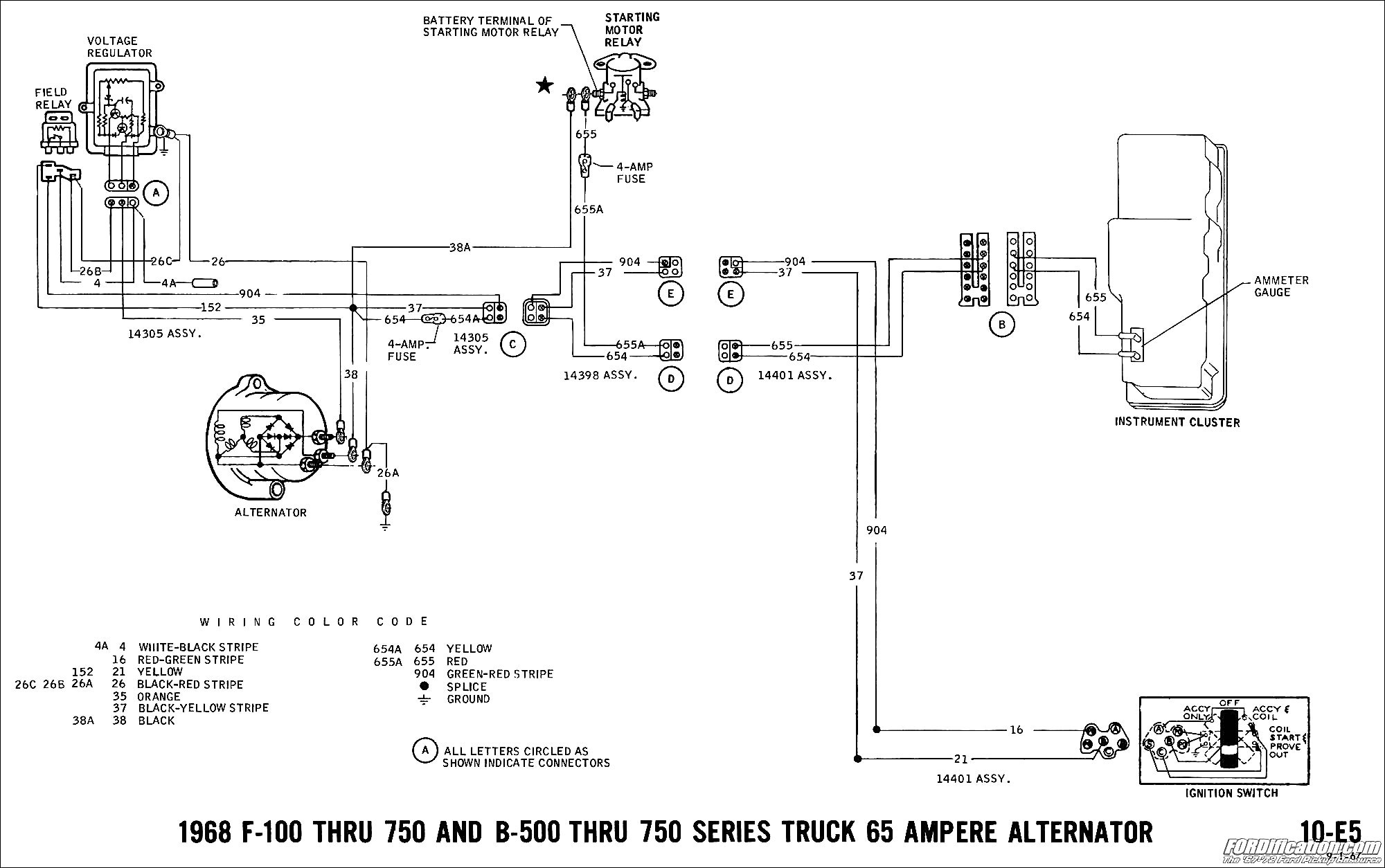
Where is the transmission fluid dipstick and filler location jcb teletruck tlt 25 many thanks davey also the wiring diagram for the alternator perkins engine. Tim hiebert friday 05 july 2019 1755 im needing a wiring diagram for jcb 930 sn 0824961 8.

66021636 Alternator Product Details Prestolite Leece
Perkins alternator wiring diagram. I am desperately looking for a wiring diagram for my perkins 4108m marine engine sn 371129901 mounted on a 1983 beneteau first 385 hull 672955. These 12 volt 70 amp alternators fit all versions including marine of perkins 4236 engines set up for a three lug mounted alternator. It uses the standard perkins wiring loom. The information herein is the property of perkins engines company ltd inc. Controller setup involves selection of such parameters as start motor run time restart holdoff time glow plug operate time before start run time after switch off signal and other parameters depending on controller model. Assortment of ac delco 4 wire alternator wiring diagram.
A wiring diagram is a streamlined traditional photographic representation of an electric circuit. Also perkins sel engine parts diagram further. It reveals the components of the circuit as simplified shapes and also the power and also signal links in between the gadgets. I just overhauled itperkins 4 wiring diagram perkins diesel engine wiring for alternator together with perkins diesel engine fuel diagrams besides perkins 4 wiring diagram furthermore 6v92 detroit engine diagram as well perkins wiring diagram alternator. Thank you all for looking and answering. And connect the red wire to the output side of the alternator 1032 stud take the long wire and connect to the side of the coil.
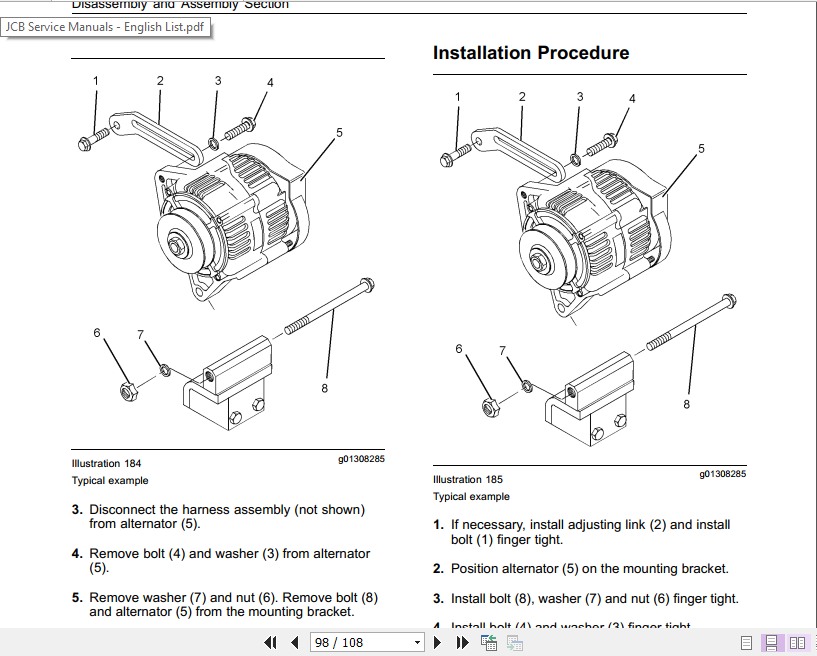
A wiring diagram to connect the gsc300 model to the perkins electropak is shown below. Any pointers to where i can get this information is welcome. The other controllers are wired similarly. Perkins engines company ltd expects that there will be some additions and modifications to this document as the engine program development continues and as oem requests for information not currently addressed are added. My main concern is the wiring for the starter motor and alternator. The adjuster arm securing bolt is at a 120 degree angle to the mounting arms as can be seen from the photos and diagram and note that the mounting bolt is on the right or left see photos.
Any advice greatly appreciated 9.


