This is accomplished by a screw in unit installed at the measuring point for optical level scanning as well as an electronic. Honda cb750 k0 k1 cb 750 electrical wiring diagram schematic 1969 1970 1971 here.

Bmc 1100 Amp 1300 Workshop Manual Vehicles Propulsion
Olc k1 wiring diagram. Normal open pink nc. Dashed lines indicate a single purchased component. An example of a wiring diagram for a motor controller is shown in figure 1. Ac fancompressor not working how to test repair broken hvac run start capacitor air condition hd duration. Honda cb750 k2 cb 750 electrical wiring harness diagram schematic 1972 here. Olc d1 is meant for keeping a specified level in a vessel by.
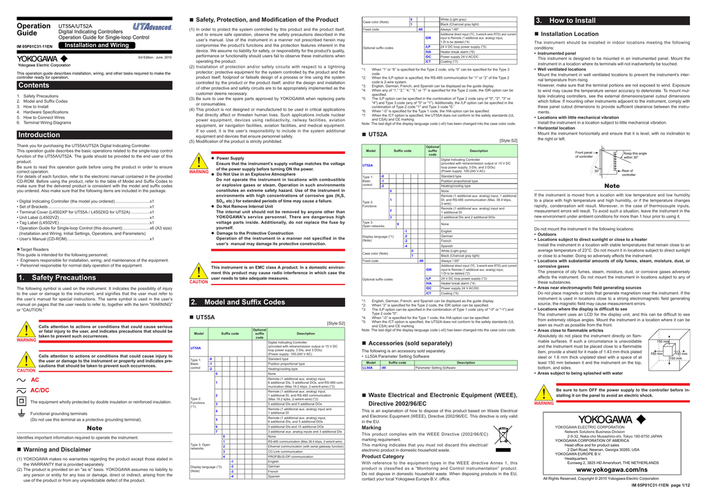
The olc d1 and olc k1 are optical level controlling de vices. Start up data sheet 28. Electronic oil level olc k1 test. 52 olc k1 optical oil level control 19 53 delta piijohnson p545 oil pressure control 20 6. This system uses 3 phase ac power l1 l2 and l3 connected to the terminals. K1 amplifier pdf manual download.
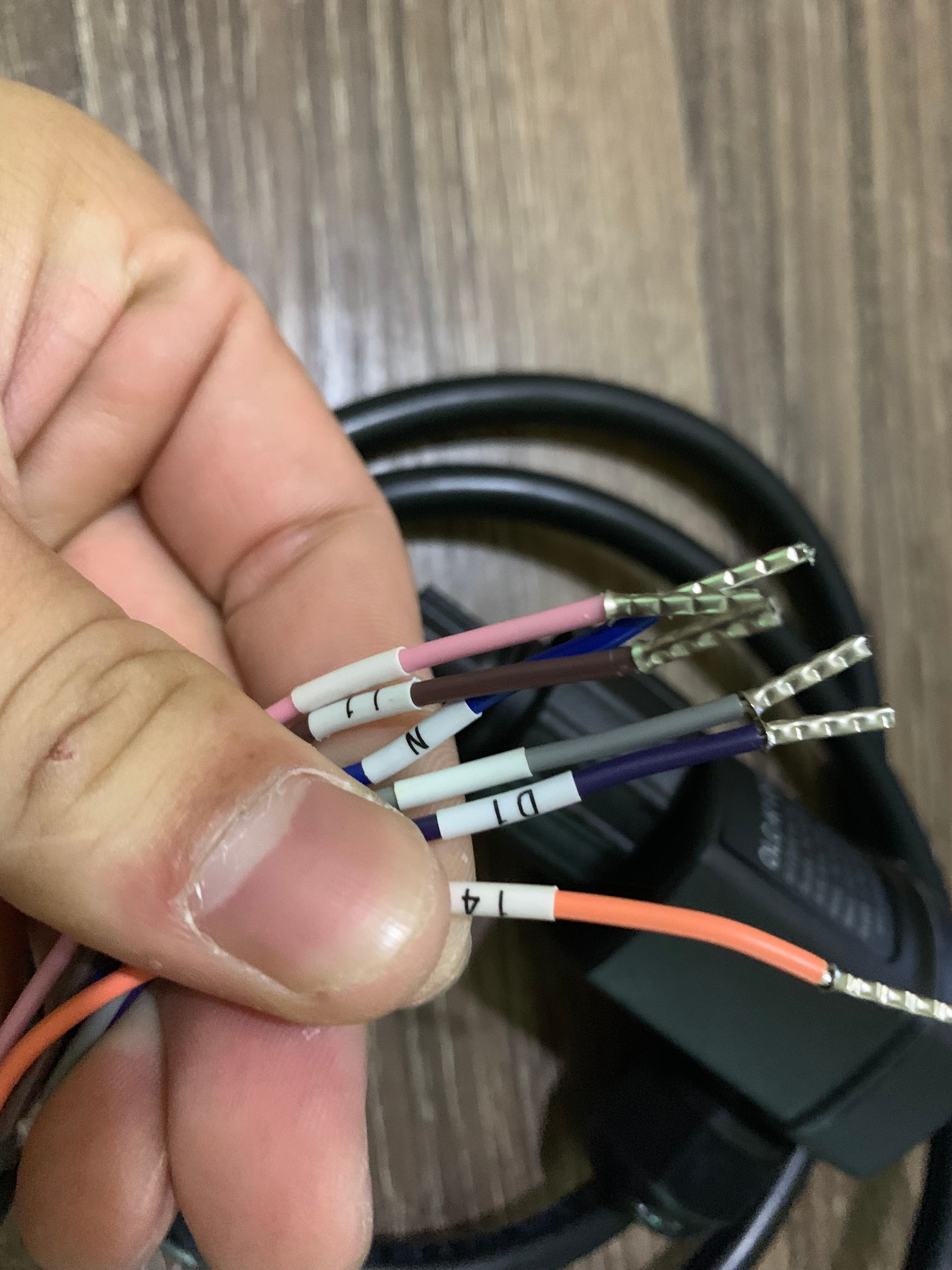
Honda cb650 sc nighthawk cb 650 electrical wiring diagram schematic 1982 1985 here. Olc k1 optical level switch sensor bitzer part no34731806 wiring diagram dimensions in mm application the olc k1 optical level switches sensor is used for contactless monitoring of the liquid level in compressors. Sche matic wiring diagram 2 fonctionnement le olc d1 s peut contrôler soit le niveau dhuile minimal soit le niveau dhuile maximal dépendant de la position de montage et de lintégration dans la chaîne de sécurité. Common signal orange no. View and download crown k1 wiring diagram online. Pour surveiller le niveau dhuile minimal et maximal en même temps deux olc d1 s doivent être installés.
Olc d1 olc k1 h2 1 1 grey violet blue brown pi nk ora g s3 reset f5 p f6 p k2t 18 f13 3 f14 5 b1 ϑ k2 k1t 11 k1 10 y1 k2 14 o p t i o n o p t o n 3 0 s c 15 d1 o n l y o l c k 1 f4 c l cn n schematic wiring diagram part winding view colour function brown l. The olc k1 is for monitoring oil level in compressors while the old d1 is for controlling levels in vessels. Wiring diagram appendix 22 25 61 terminal box wiring diagram 22 62 wiring se b3 olc k1 and delta pii monitoring devices 23 63 wiring the int280 oil level regulator 25 7. Cb750 k0 1969 1970 cb750 k1 1971 cb750 k1 k5 1971 1975 cb750 k2 1972 cb750 k3 k7 1973 1977 cb750 k6 1976 cb750 k7 1977 cb750. Wiring diagrams engine tune up periodic maintenance. Note that symbols are discussed in detail later.
The relay in olc k1 is used in the safety chain for the compressor and will open and lock out in case of a failure. Honda cb750 hondamatic cb 750 a electrical wiring diagram schematic 1976 1978 here. Richard lloyd 2607803 views. Head bolt torque sequence diagram. The three phases are then connected to a power interrupter.
