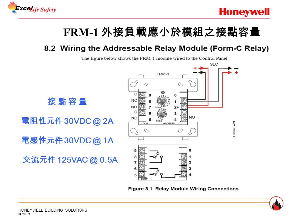
Some control panels have relay built in and do not require external wiring. Break wire run to provide supervision.
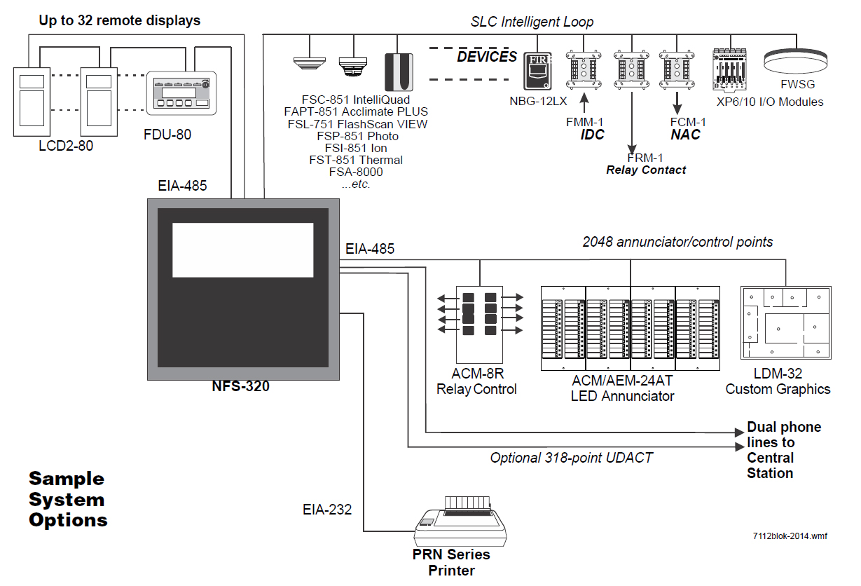
Notifier Control Module Wiring Diagram Notifier Fcm 1 Wiring
Notifier control module wiring diagram pdf. One relay required for each circuit. Install module wiring in accordance with the job drawings and appropriate wiring diagrams figures 3 10. Fcm 1 module see wiring diagram fig. The frm 1 relay control module is intended for use in intelligent two wire systems where the individual address of each module is selected using the built in rotary switches. Module does not supervise controlled. Refer to the appropriate notifier control panel installation note.
Our notifier cmx 2 addressable control module in new condition comes with a warranty of 90 days and fast shipping via ups. Install module wiring in accordance with the job draw ings and appropriate wiring diagrams. The frm 1a addressable relay. Scs 8 fan control module annunciator. Intelligent addressable control module and relay with built in type identification for onyx series panels. Some panels support.
Refer to notifier manual. Trol module provides notifier intelligent fire alarm control pan els a circuit for notification appliances horns strobes speakers etc. 15 to 32 vdc. Set the address on the module per job drawings. Module polarities are shown in alarm connect modules to listed compatible 32 vdc max. Some panels support this module can be used to replace a cmx 2 mod a ule thatdisconnect power to the control panel before installing the modules.
Is recommended 24 vdc circuit 3 4. Addressability al lows the fcm to be activated either manually or through. All wiring must conform to applicable local codes ordinances and regulations. Typicalnotifier system control panel only list available from notifier. Box and the control module must be placed into the barrier and at tached to the junction box figure 2a. Notifiers intelligent addressable control module provides supervised monitoring of wiring to load devices that require an external power supply to operate such as horns strobes or bells.
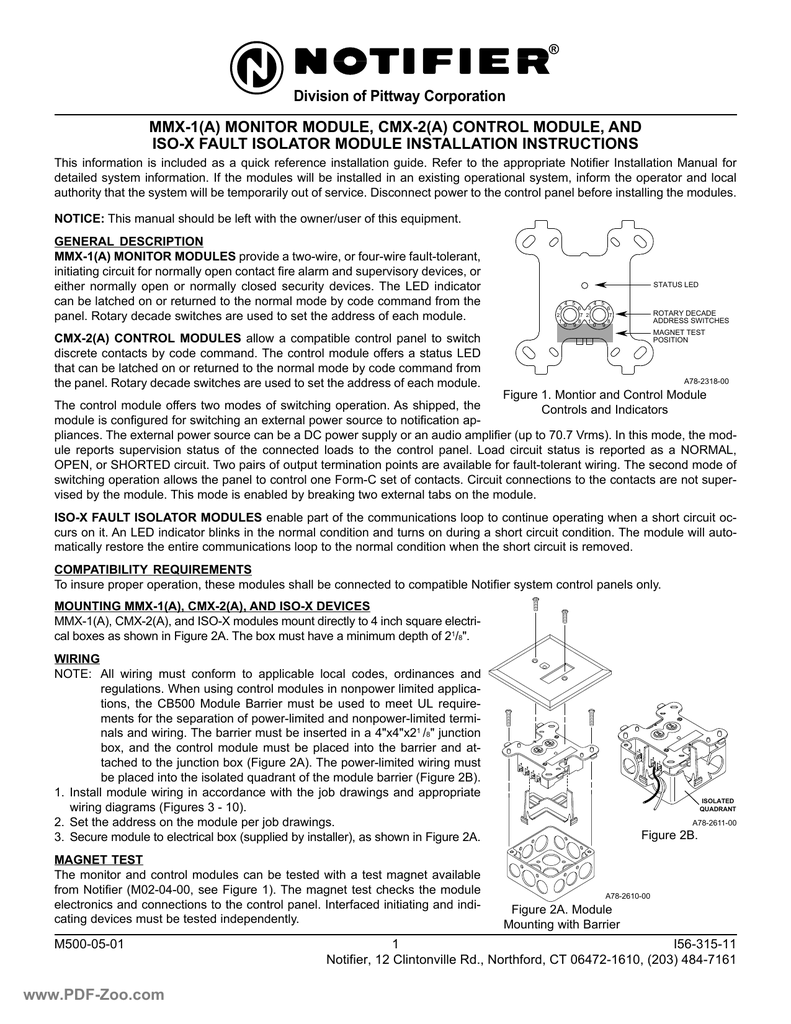
Install module wiring in accordance with the job drawings and. Notifier cmx 2 control module wiring diagram division of pittway corporation mmx 1a monitor module cmx 2a refer to the appropriate notifier installation manual for detailed system information. Notifier cmx 2 addressable control. The power limited wiring must be placed into the isolated quadrant of the module barrier figure 2b. 65 ma led on. In addition this module is intended for powerlimited wiring only.
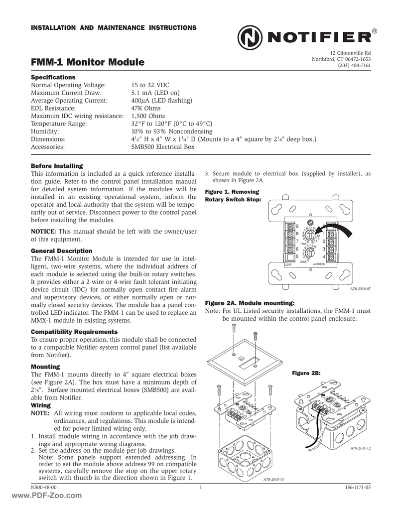
This module is intend ed for power limited wiring only. 5 for frm 1 general fcm 1 control module the fcm 1 addressable control module provides notifier intelligent control pan els a circuit for notification appliances horns strobes speak ers etc or to monitor a telephone circuit. Set the address on the module per job drawings. Install module wiring in accordance with the job drawings and appropri ate wiring diagrams. To next control module or end of line relay. Addressability allows the fcm 1a to be acti vated either manually or through panel programming on a select zone or area of coverage basis.

