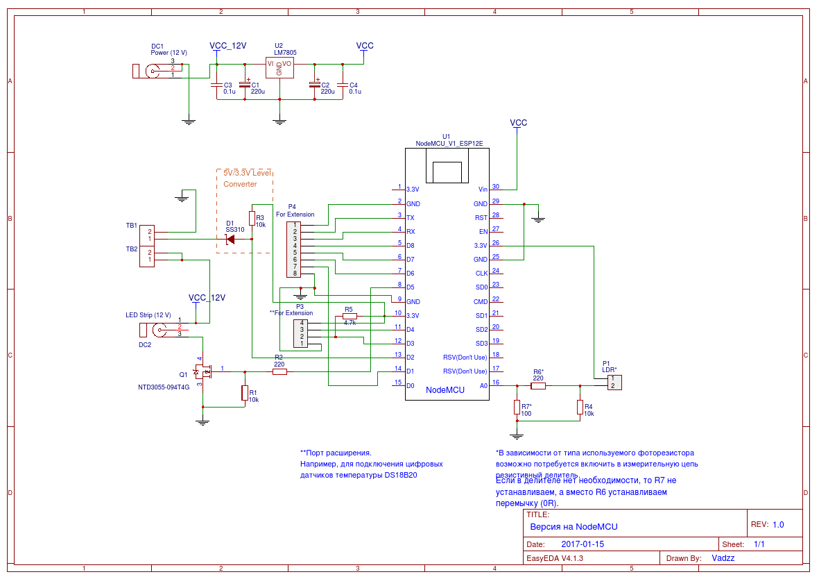
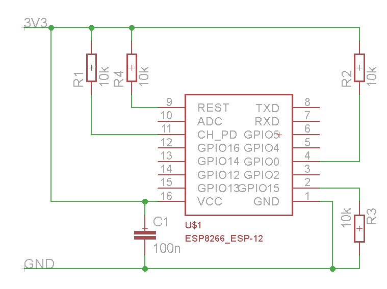
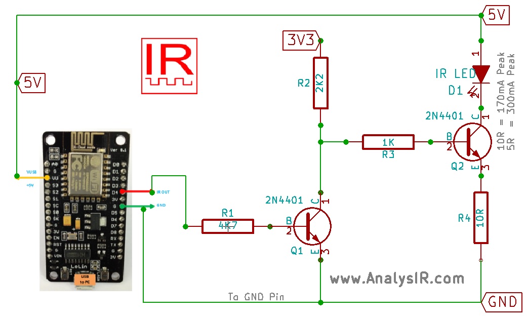
The nodemcu is an arduino compatible board that features the esp8266 at its core. Nodemcu power supply circuit diagram.

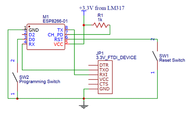
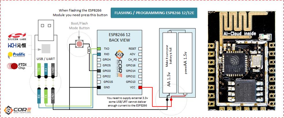
Ftdi Esp8266 Definitive Wiring 3 Steps Instructables
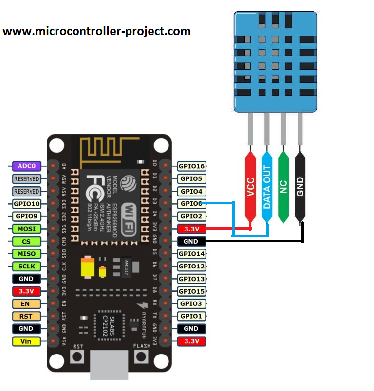
Nodemcu wiring diagram. The usb cable provides 5vdc to the embedded boards which steps down the main source voltage to 33vdc. Please like share and subscribe para meron pang. Two 470uf capacitors are connected at the input and output of the voltage regulator. Wiring guide on how to connect coinslot to your nodemcu esp8266. The overall objective in wiring the esp8266 nodemcu to the microbit is to use one power supply. This is the first version of the nodemcu board featuring the esp 12.
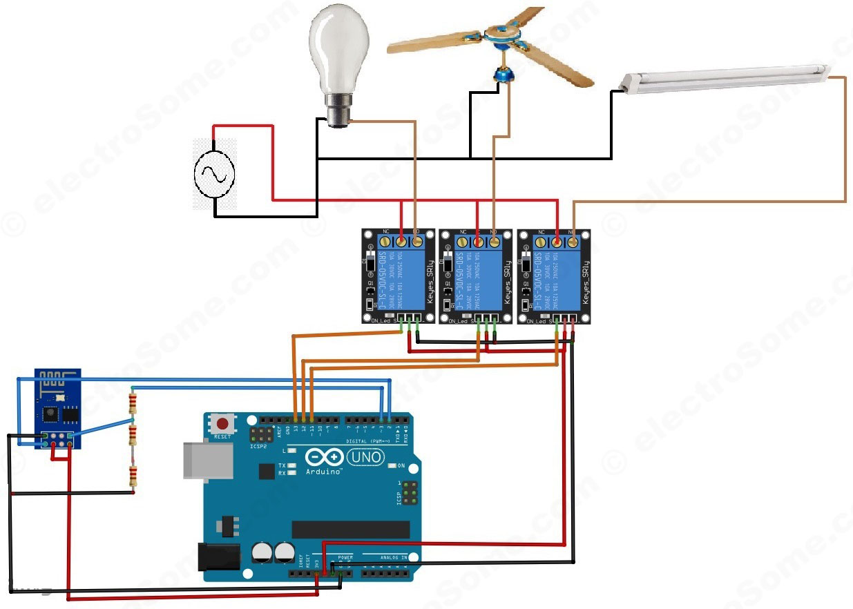
The circuit diagram is really simple as you can see. Connect esp8266 nodemcu gpio d0 pin to in1 of relay 1 in board connect esp8266 nodemcu gpio d1 pin to in2 of relay 2 in board connect esp8266 nodemcu gpio d2 pin to in3 of relay 3 in board connect esp8266 nodemcu gpio d3 pin to in4 of relay 4 in board connect power source to esp8266 and realy board. It became popular because it is a wifi ready microcontroller by itself no need for an arduino. The power supply as you can see is based on the lm7805 voltage regulator. Hindi po ito diy kung papanu gumawa ng diy wifi vendo na plug play. The nodemcu and the microbit are both powered by a 33vdc voltage source obtained from a usb cable.
J1 is the female dc socket where you can connect a 12v adaptor or a 12v battery or a 9v battery.


