Wire type and wire installation tips. Selected wiring diagrams under documents attention.
Wiring Diagram For Neumax Actuator Qt Find Wiring Diagram For
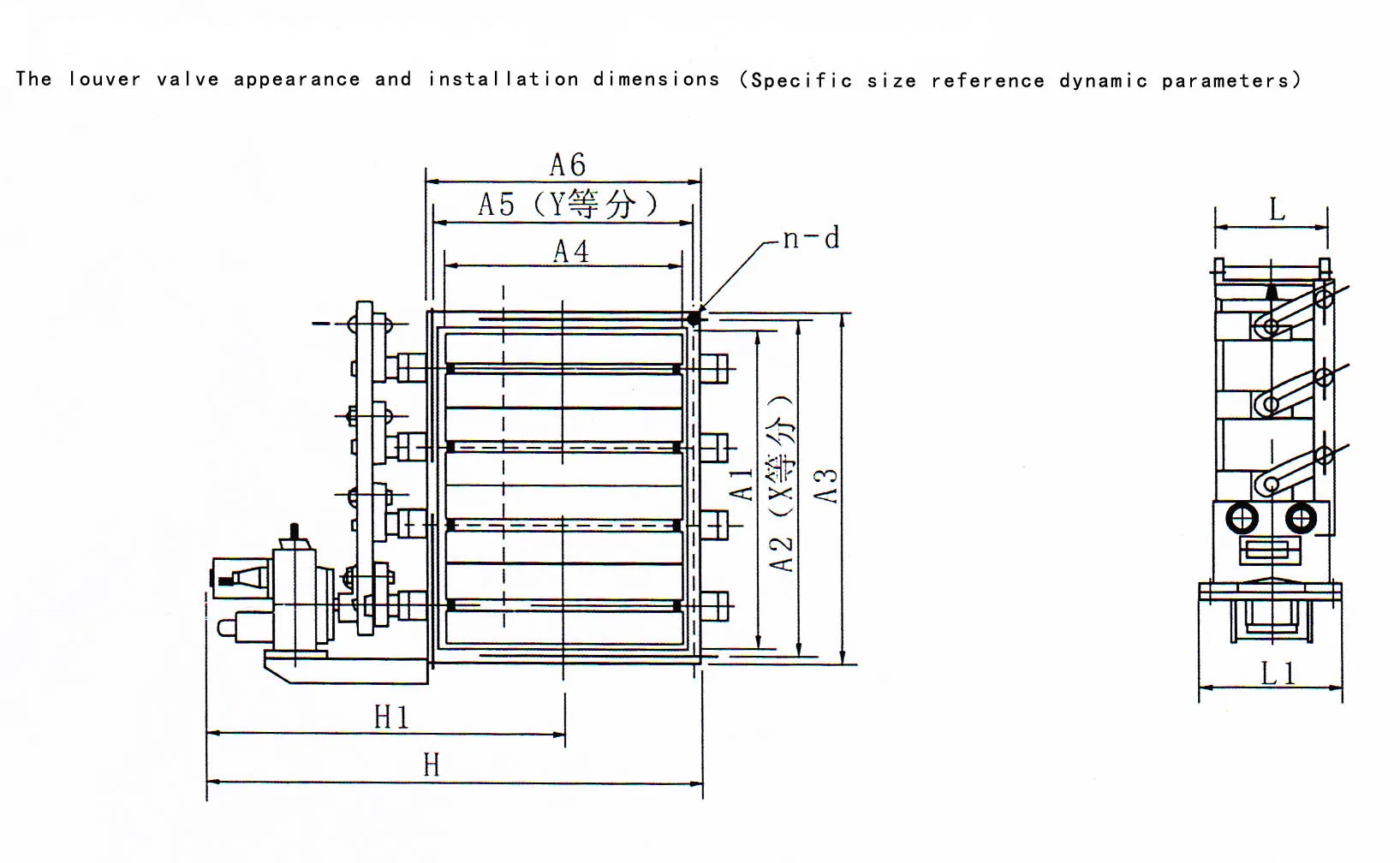
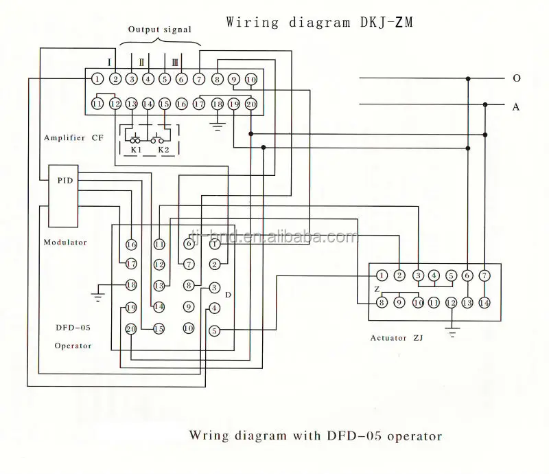
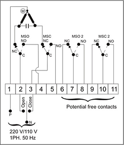
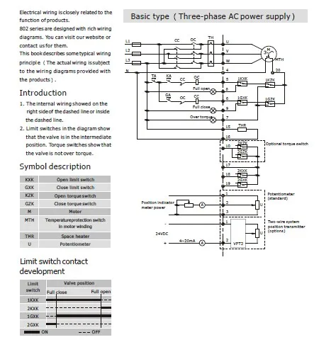
Neumax actuator wiring diagram. Wiring diagram number quotation number. The angle of electrical actuator installation must be between 0180 degree. A wiring diagram is a streamlined standard photographic representation of an electric circuit. Neumax qt series quarter turn electric actuator. Qt series electric actuators are designed engineered for robust reliable and for high performance duty onto quarter turn valves. By using this site you agree to the usage of cookies.
Modulating service with tcm. Neumax 1 enclosure standard enclosure to water jet proof water tight proof ip 67nema 46 2 motor squirrel cage motor is of encapsulated type on high stall torque and low inherent force for seating unseating of valves. All motors are integrated with build in thermal protection. Common wiring diagrams. The following common wiring diagrams are available. The scenario is wiring your actuator to a 3 way toggle switch.
Electric latch retraction with auto operator. Rotork wiring diagram selector. Auto operator amd latch retraction wiring. Double door alk wiring. 1 wires from all actuators are tied together and tied to the negative leg of the control signal. The next set of wires is your black wire keeping in mind the same configuration diagonally as the red wires should be on the opposite side.
For quarter turn valves automation used in heating ventilation air conditioning water treatment works power generation petrochemical plants oil storage facilities chemical plants effluent treatment works pulp paper mills and shipbuilding industry. The transformers are properly sized. Collection of linear actuator wiring diagram. Delayed egress fire rated application. The wiring diagram opens in a pop up window. Check for correct voltage prior to wiring.
You should connect them diagonally from each other in simpler terms think of it as a backslash or forward slash. Use sealant to seal conduit connections after wiring to prevent dusting or water contamination. For further information please refer to our privacy policyprivacy policy. Multiple actuators positioned by the same control signal may be powered from multiple transformers provided the following rules are followed. Close we use cookies in order to optimise this website and for continuous improvement. It reveals the components of the circuit as streamlined shapes as well as the power and also signal links in between the devices.
Start connecting the red wires. One single door with panic bar. Please enter the address of our website in the address of web site to allow box. Do not install upside down or below the horizontal. If the pop up blocker is turned on in your browser you are not able to view the wiring diagram. Turn power off before servicing or for maintenance purpose.
Card reader actuator auto operator. The unique reliable motor module adjustable cam plate limit switch self locking.
Gallery of Neumax Actuator Wiring Diagram