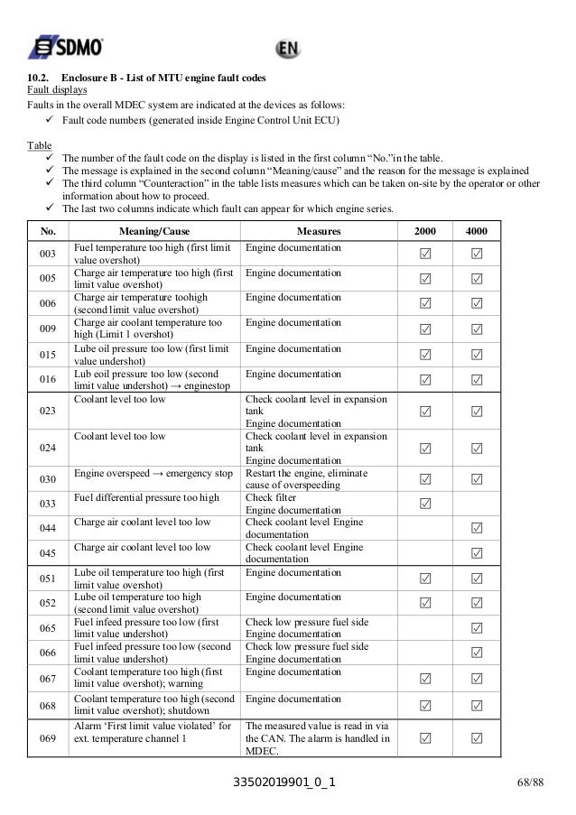
All control display and communication signals are in interface cable w004 mdec connector x1. The mdec governor is protected by a 20 a automatic cutout via cable w003 connector x5.

Hot Item Mtu Engine Control Unit Mdec Mtu Mpc Ecu X00e50209114 76 X00e50211110 76 5275307654 Governor Detroit Diesel Mtu Elektronik 5275307654 76
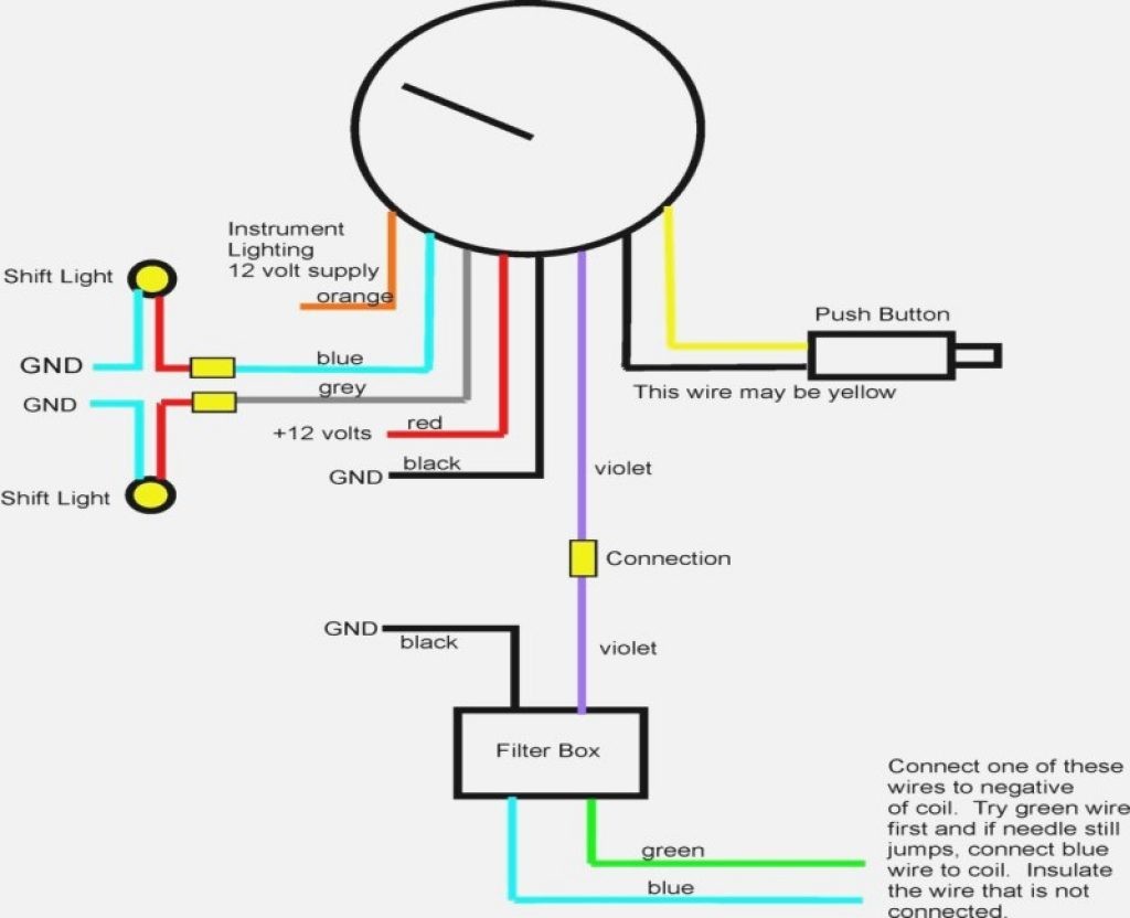
Mtu mdec wiring diagram. Engine control system mdec for stationary generator engines is used for engine series mtuddc br 4000 and ddcmtu br 2000. ø controlling the diesel engine. 322 option h5 or h13. 32 multi line 2 based products 321 terminal description this description relates to the products agc 3 agc 4 gpc gpu ppm and ppu. Mtu 4000 mdec control unit wiring diagram free download of mtu 4000 mdec control unit wiring diagram you can read the recommendations from the user guide schematic diagram the technical guide or perhaps 20004000 series detroit how many hours before. Engine management system mdec primarily fulfills the following tasks.
Daimlerchrysler off highway mtu assuring you. Mtu 4000 mdec control unit wiring diagram free download of mtu 4000 mdec control unit wiring diagram you can read the recommendations from the user guide schematic diagram the technical guide or perhaps mtu series 4000 mdec codes tricia joy alarms mtu mdec series 20004000 free fuller 9 speed transmission. Option h7 is a limited version of h5 which does not include mtu mdec or mtu adec module 501 h13. Iso 9001 certification quality assurance in designdevelopment production installation and service. Latest mtu adec sam wiring diagrams updates mtu mdecadec and 1 test answers baystat052a owners manual bobcat t 300 fuel tank broward ecu j1939 interface 15 16 automatic or manual startstop of the i cb cat diesel cat gas mtu mdec deutz teme communication bridge for the. 00 02 0878 section 75 2013 03 07.
Option h7 is not available for agc 100 cgc 400 and gc 1f. Genset controller unit model ems gc10. 17 77788 kb download. Mdec engine control system br 2000 br 4000 stationary generator engines s structure and function s operation s maintenance and repair s operating personnel s plant personnel documentation parts 1 2 3 e 531 711 01 e. Ecu4 mtu wiring diagram. The pim modules are wired to a separate 10 a fuse see mtu wiring diagram.
32 multi line 2 based products 321 terminal description this description relates to the products agc 3 agc 4 gpc gpu ppm and ppu. ø monitoring the operating states. Option h7 is a limited version of h5 which does not include mtu mdec or mtu adec module 501 h13. Option h7 is not available for agc 100 cgc 400 and gc 1f.


