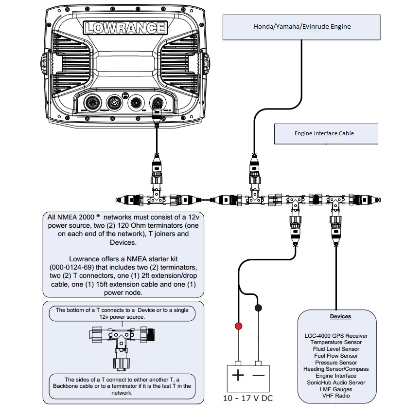
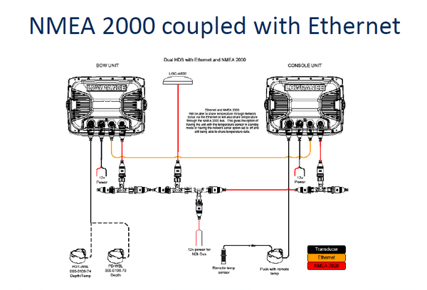
The wiring diagram on the opposite hand is particularly beneficial to an outside electrician. Home decorating style 2020 for lowrance hds 5 wiring diagram you can see lowrance hds 5 wiring diagram and more pictures for home interior designing 2020 176748 at manuals library.
Lowrance 2000c Gps Manual
Lowrance hds 5 wiring diagram. Hds 5 hds 7 units nmea wiring data cable to exchange nmea data the hds 5 and hds 7 units have a nmea version rs communication port. Wiring diagrams for conventional non chirp transducers. If so you can simply. Check to see if an adapter cable exists see the adapters page. Lowrance hds 5 wiring diagram. Lowrance model elite 5 hdi the additional wires are for nmea data transfer to and i am replacing an old lowrance with a elite 7x i need the wiring diagramdownloads product series please select accessories ais autopilot broadband 3g radar broadband 4g radar elite hdi chirp elite ti2 elite ti fishhunter gps halo radar hds gen1 hds carbon.
Lowrance hds 5 manuals manuals and user guides for lowrance hds 5. Wiring diagram lowrance elite 5 hdi you are welcome to our site this is images about wiring diagram lowrance elite 5 hdi posted by ella brouillard in wiring category on nov 14 you can also find other images like wiring diagram parts diagram replacement parts electrical diagram repair manuals engine diagram engine scheme wiring. Serial communications port one com 1 can be used to transmit or receive nmea format data. We have 5 lowrance hds 5 manuals available for free pdf download. Sometimes wiring diagram may also refer to the architectural wiring program. Check to see if the transducer is a mix and match 600w or 1kw model.
Hds 5 hds 7 units nmea 0183 wiring data cable to exchange nmea 0183 data the hds 5 and hds 7 units have a nmea 0183 version 20 rs 422 communication port. Wiring diagram for fish finder wiring diagram for lowrance hds 5 wiring diagram for lowrance hds 7 wiring diagram for lowrance structure scan wiring diagram is a technique of describing the configuration of electrical equipment installation eg electrical installation equipment in the substation on cb from panel to box cb that covers. Wiring diagrams for conventional non chirp transducers. Data cable wiring diagram. Page 26 data cable wiring diagram. The simplest approach to read a home wiring diagram is to begin at the source or the major power supply.
Serial communications port one com 1 can be used to transmit or receive nmea format data. Before attempting to rewire a transducer connector you should. These diagrams are for the use of professional installers. Operation manual installation manual installation instructions manual quick start manual.


