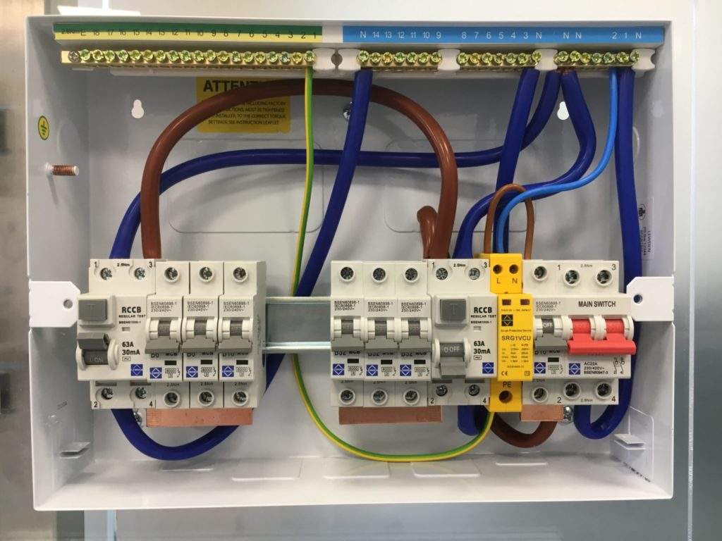
Available in both 2 pole and 4 pole versions type b residual current circuit breakers rccbs provide total protection for all known residual current faults. Spd wiring configuration 2.

What Is An Rcbo And How Does It Work Residual Current
Lewden spd wiring diagram. Diagram dd4 low speed low speed u1 u1 v1 v1 w1 w1 u2 u2 v2 v2 w2 w2 l1 l1 l2 l2 l3 l3 e e high speed red leads red leads black leads black leads diagram dd3 two speed motors in dahlander connection tapped winding. Type 1 spd is characterized by a 10350 µs current wave. Add a review cancel reply. Single speed only 3ø wiring diagrams u1 red v1 yellow w1 blue thermal contacts tb white l1 l2 l3 n e codes. The type 2 spd is the main protection system for all low voltage electrical installations. Required fields are marked.
Lewden offer a three phase versionwe have emailed you a copy of the wiring diagram for the lewden 3 phase surge protector srg3v1g kind regards stuart higgins crown electrical supplies ltd. Lewden has recently introduced type b rccbs to its range of circuit protection devices in addition to the type a and type ac versions. When conduc ng insula on resistance tests on the installa on remove either the plug in cartridge or the earth cable to the device. Spd wiring configuration 1. Your email address will not be published. Input and output conductors physically well separated and connected on the same terminal.
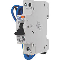
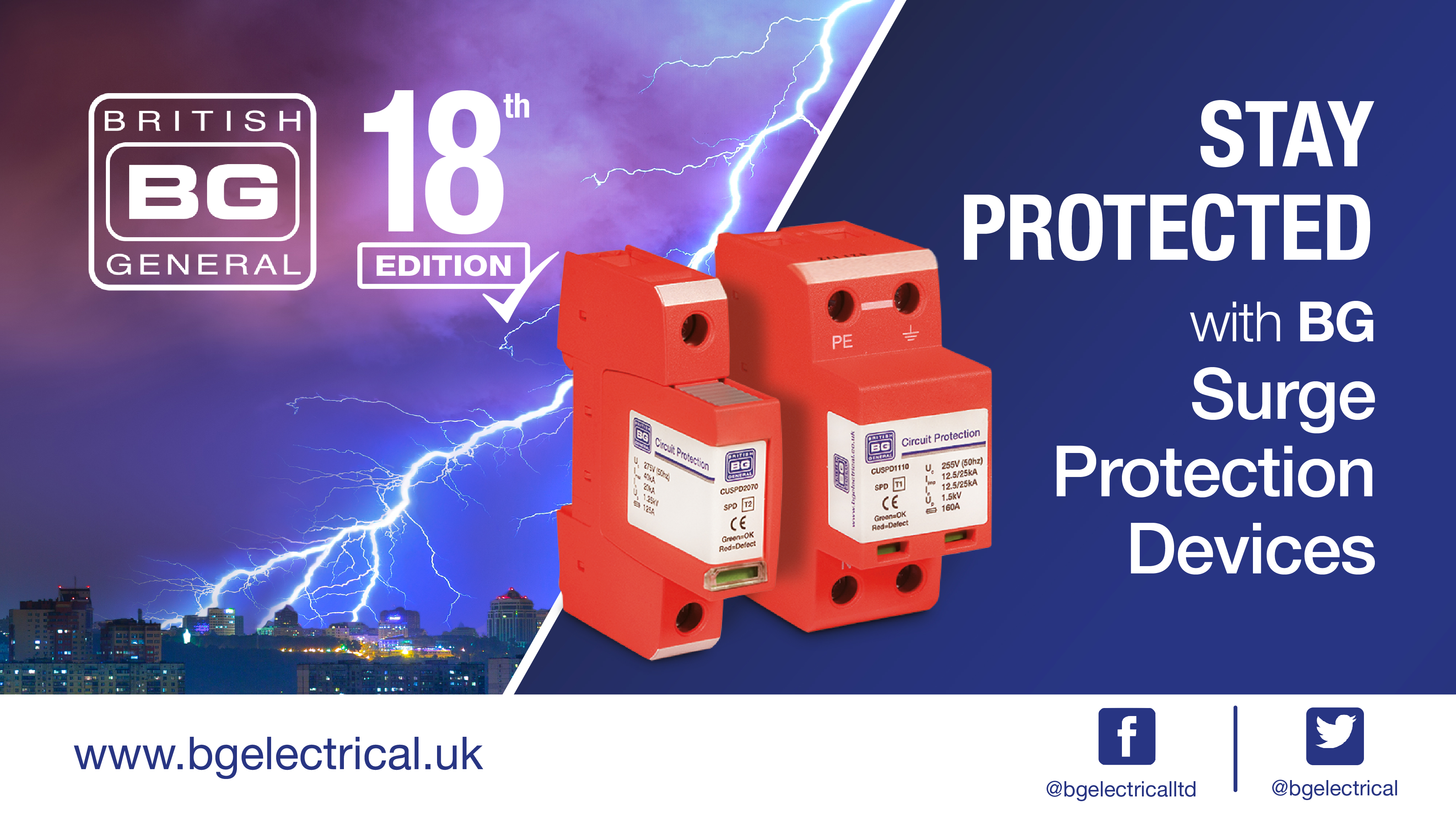
In this single phase home supply wiring diagram the main supply single phase live red wire and neutral black wire comes from the secondary of the transformer 3 phase 4 wire star system to the single phase energy meter note that single phase supply is 230v ac and 120v ac in us. With the latest edi on of the iet wiring regula ons for electrical installa ons bs7671 for consumer unit installa on use in conjunc on with lewden mcb type b16 1p part number g06 1b16 important. Type 2 spd is characterized by an 820 µs current wave. These two lines line and neutral from energy meter are connected to the double pole mcb isolator switch. Wiring diagram since wiring connections and terminal markings are shown this type of diagram is helpful when wiring the. Installed in each electrical switchboard it prevents the spread of overvoltages in the electrical installations and protects the loads.
Two speed one winding vt or ct ms single voltage. Popular forums electricians forum electrical forum electricians forums sponsors forum sponsor news offers electrical tools and products electric underfloor heating wiring electrical engineering chat lighting forum electrician resources and downloads professional electrician security alarms door entry and cctv public commercial electrical. Spd wiring configuration 1. Two speed one winding chp ms single voltage. Upstream and downstream conductors connected on the voltage surge protector terminal with a common path.
