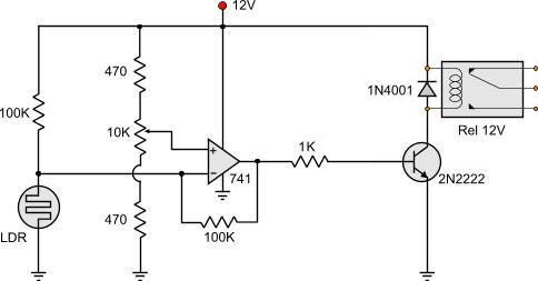
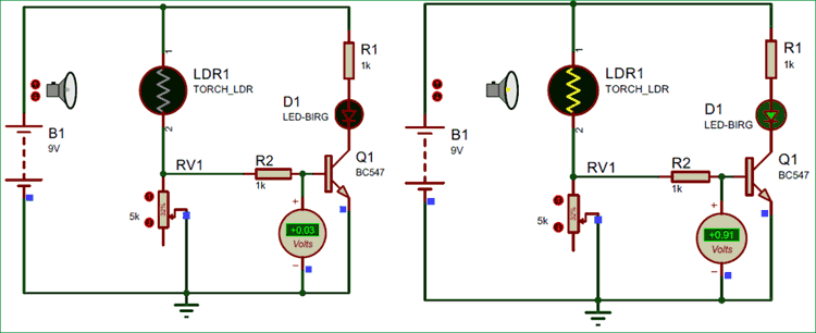
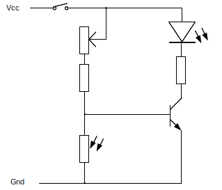
When transistor q1 is on by conducting even small current on base the output of transistor q2 is low off. In the morning time this sensor has a low resistance around 100ω.
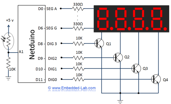
Day3 Seven Segment Led Circuit Diagram Embedded Lab
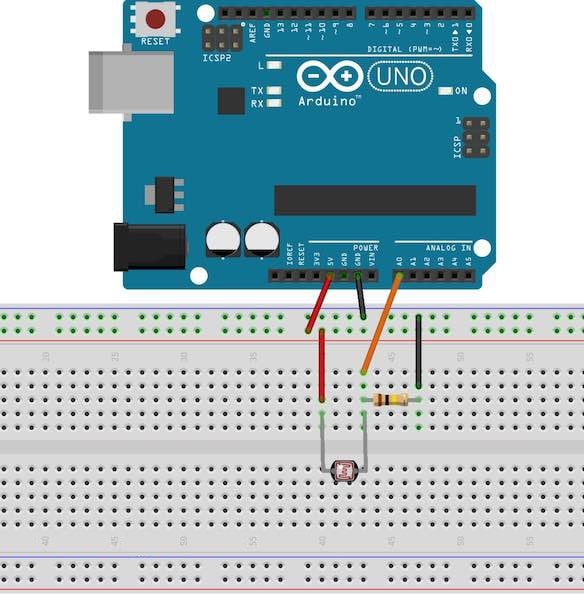
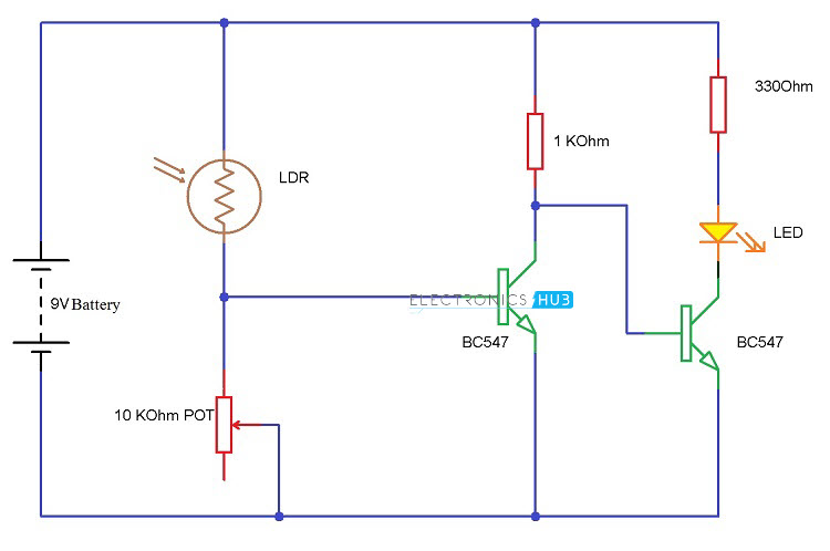
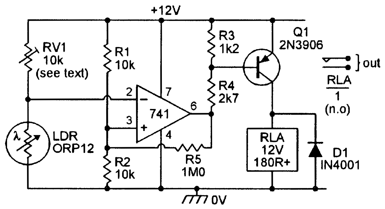
Ldr wiring diagram. A voltage divider made using ldr ldr1 and a potentiometer rv1 b output led d1 in our switching circuit made using a. The ldr circuit diagram works like this. Light detector sensor circuit diagram. The circuit can be used to switch on incandescent garden light bulbs at desk and switch off them at dawn. As you can see in the ldr circuit diagram it can be a distinguished as two smaller circuits. This makes the voltage at the base of the transistor too low to turn the transistor on.
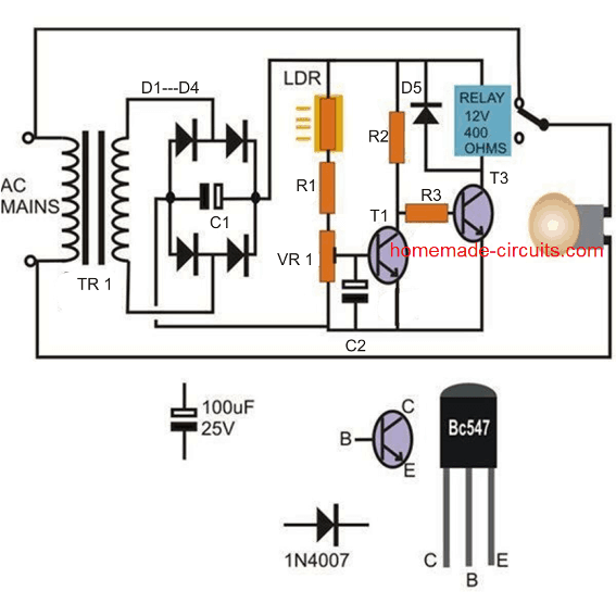
Ldr is a special type of variable resistor which value can be increased or decreased according to light falling on it. Therefore no current will go from the collector to the emitter of the transistor. Transistor q1 and transistor q2 are connected as not gate. How the ldr circuit diagram works. Circuit of a compact and true solid state automatic lawn light is described here. As its specified property ldr act as the light and dark sensor.
When its dark the ldr has high resistance. A 10 mm encapsulated light dependent resistor ldr here works as the twilight detector. Thus the power supply flows through the ldr ground through the variable resistor and resistor as shown in the above light sensor circuit. Ldr is light dependent resistor. Light dependent resistor circuit diagram. Ldr circuit diagram at day when light falls on ldr then conductivity increased and current flows between supply to the base of the transistor and then transistor q1 will on.
The circuit of light detector is very simple and easy to build with very few components. When light falls on ldr the resistance of it goes very high about in mega ohm.
Gallery of Ldr Wiring Diagram