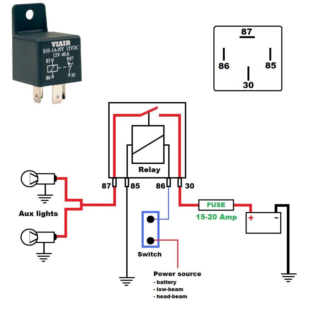
From this point forward ladder dia. Leave no bare wire.

Wrg 2228 Wiring Diagram For A Off Delay Timer
Ladt2 wiring diagram. The switch allows for energizing the top bulb only the night light only both bulbs at once or for turning both bulbs off. Dcc wiring clinic 9 dcc wiring basics ii with just one large block wiring mistakes and failures can be very hard to locate one defect anywhere and its no go everywhere. Its likely though youve already read the wikipedia page about series and parallel circuits here maybe a few other google search results on the subject and are still unclear or wanting more specific information as it pertains to leds. This differs a schematic layout where the arrangement of the elements affiliations on the layout usually does not match to the parts physical. Tesys d time delay auxiliary contact block 1 no 1 nc screw clamp terminals show more characteristics. The first and most common is the ladder diagram so called because it looks like the symbols that are used to represent the components in the system have been placed on the rungs of a ladder.
Compare the maximum number of products that can be compared is 4. Operation working of automatic star delta starter. Check for short circuits as you go before the booster is connected. Tesys d time delay auxiliary contact block 1 no 1 nc screw clamp terminals show more characteristics. Control 3 phase motor from more than two places power control diagrams. The top socket a holds a standard incandescent bulb.
Remove already added products. Add to my products remove from my products. Be very careful in wiring methods and workmanship. Wiring a 2 bulb lamp switch. Types of wiring diagrams there are three basic types of wiring diagrams used in the hvacr industrytoday. Stardelta starter without timer power control diagrams wiring diagrams.
Remove already added products. The second socket b typically holds a small low wattage bulb similar to a night light bulb. Customers also buy these products. Add to my products remove from my products. From l1 the phase current flows to thermal overload contact through fuse then off push button on push button interlocking contact 2 and. Simple multi meter is fine.
This diagram illustrates the wiring for a bedside lamp with two sockets. For adapting existing wiring to a new product without coil suppression lad4bb 004 0019 with coil suppression ac 24 to 48 v lad4bbve 003 0014 ac 50 to 127 v lad4bbvg 003 0014 ac 110 to 250 v lad4bbvu 003 0014 electronic serial timer modules mounted using adaptor lad4bb to be ordered separately see listing above. Compare the maximum number of products that can be compared is 4. Wiring diagram book a1 15 b1 b2 16 18 b3 a2 b1 b3 15 supply voltage 16 18 l m h 2 levels b2 l1 f u 1 460 v f u 2 l2 l3 gnd h1 h3 h2 h4 f u 3 x1a f u 4 f u 5 x2a r. A wiring diagram usually gives information regarding the relative placement and also setup of gadgets and also terminals on the gadgets in order to help in structure or servicing the device. Hopefully those looking for practical information on electrical circuits and wiring led components found this guide first.


