Kk2 board wiring diagram. Im in the final stages of completing my 3d printed multirotor that im building for a school projecti have a question about how to wire my receiver.
%2C445%2C291%2C400%2C400%2Carial%2C12%2C4%2C0%2C0%2C5_SCLZZZZZZZ_.jpg)
Orangerx Kk2 Wiring Diagram Siosioppitur Aerox Zografisch Nl
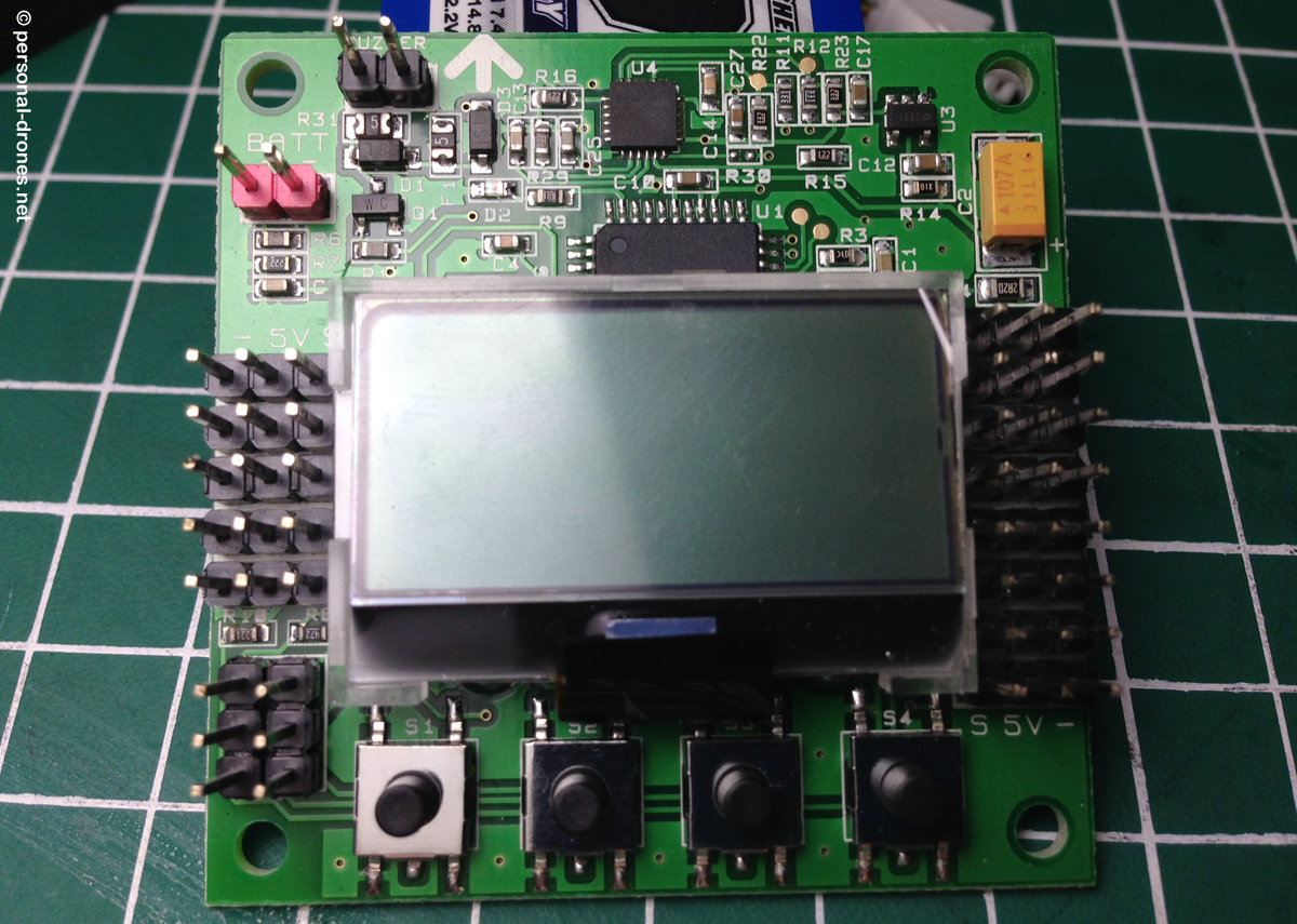
Kk2 wiring diagram. The next evolution of the rotor revolution is here. The kk is a very popular flight controller as its cheap works well and one is the manual from hobbyking and has some useful diagrams. Designed exclusively for hobbyking by the grandfather of the kk revolution rolf r bakke the kk21 is the next evolution of the first generation kk flight control boards and has been engineered from the. New kk215 board wiring setup and some fun at the end. Design diagram software wiring edraw is an effective engineering representation manufacturer that aids to picture industrial systems in electronic devices electrical chemical procedure as well as mechanical design. Buzzer which is used for alarms is connected to the 2 pins top left of the board and the voltage input in my case taken from the power distributer board for the escs connected to the one just below and to the left.
Quadcopter using kk 215 module. Looking at the diagram note each motors number. Kk2 wiring whats new. While that may not seem like much it actually eliminates a lot of currently existing commercial civilian drones available to t. The black wire for each esc plug goes on the right side of the connection near the is a huge problem that i cant. Kk2 wiring diagram the kk2 board is whats known as a flight controller which is basically the the things you need to know is labelled on the diagram below.
The kk21 is packing new found power with updated sensors memory and header pins. For a drone to fly autonomously all the necessary sensors processing power and communication chips must be built in. Its goal is to visually connect concepts style and style of complex commercial design systems to. I also go over setting up the voltage alarms once you have connected the power lead. In this video i go over how to attach a power lead to the kk2 board so the board can monitor battery voltage. Signal wire like the reciever is is the pin closest to the screen followed by 5v in the centre and 0v on the right.
Transmitter receiver flight controller fpv camera fpv transmitter and antenna fpv receiver and monitor or goggles. Check above diagram which show you a sample fpv quadcopter and some parts.


-700x700.jpg)


