The source is at the switches and the input of each is spliced to the black source wire with a wire nut. Find the user manual and the help you need for the products you own at manualsonline.

Yc 8355 Porsche 914 Fuel Injection Wiring Diagram Wiring Diagram
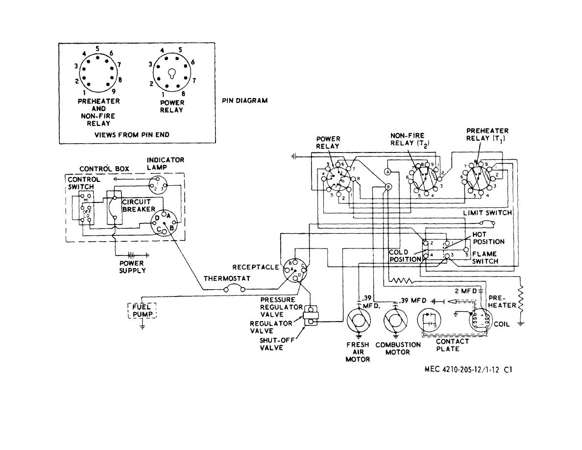
Jet fan wiring diagram. Disposal 9 110 connection diagrams 10. From the switches 3 wire cable runs to the ceiling outlet box. Take a closer look at a ceiling fan wiring diagram. Collection of fantech wiring diagram. Manuals and free owners instruction pdf guides. Ceiling fan wiring diagram.
Fantech wiring diagram fantech fan wiring wire center u2022 rh silaiwala co fantech dryer booster fan fantech fans 4. With these diagrams below it will take the guess work out. Click on the image to enlarge and then save it to your computer by right clicking on the image. 3ø wiring diagrams 1ø wiring diagrams diagram er9 m 3 1 5 9 3 7 11 low speed high speed u1 v1 w1 w2 u2 v2 tk tk thermal overloads two speed stardelta motor switch m 3 0 10v 20v 415v ac 4 20ma outp uts diagram ic2 m 1 240v ac 0 10v outp ut diagram ic3 m 1 0 10v 4 20ma 240v ac outp uts these diagrams are current at the time of publication. Acme is the leading supplier of air movement equipment in more markets than any other because acme is able to design ventilation equipment for specific applications and requirements. Fault finding 9 91 electrical 9 92 mechanical 9 10.
This wiring diagram illustrates the connections for a ceiling fan and light with two switches a speed controller for the fan and a dimmer for the lights. This might seem intimidating but it does not have to be. Usa made jet fan attic master flow thermostat wiring diagram top 5 best roof mounted attic fans channel master wiring diagram masterflow thermostat to a box fan. Two conductors a positive from the battery switch with a fuse and a negative from the ganged together battery negatives should be ran to where the central switch panel is. Fan power and ground. Page 4 optional relay overrides temp sensor and turns on fans when ac is turned on battery 86 30 87 85 86.
Pick the diagram that is most like the scenario you are in and see if you can wire up your fan. 52 fuses wiring 5 53 speed control 5 54 overheat protection 5 55 emergency use fans 6 56 switch on 6 60 maintenance 7 70 infrequent use 7 80 overhaul extended maintenance 9 9. Suggested electric fan wiring diagrams page 1 these diagrams show the use of relays onoff sensors onoff switches and onoff fan controllers. The next step is to get the power from the house battery up to the switch panel where we can use it to do some good.


.jpg)


