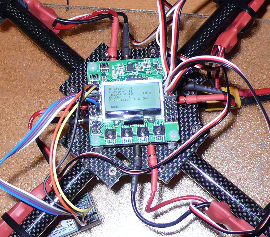
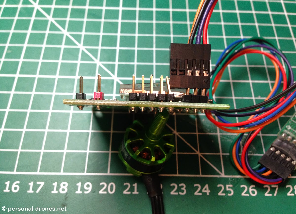
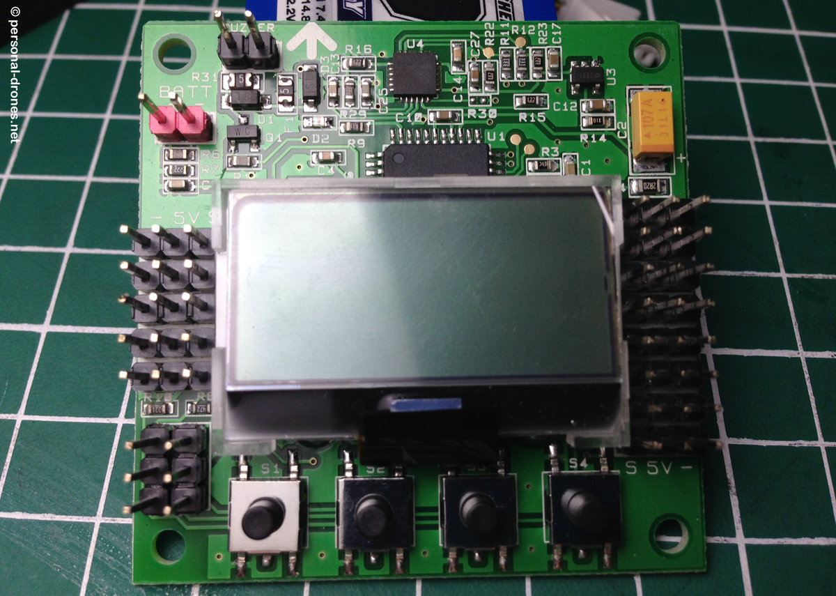
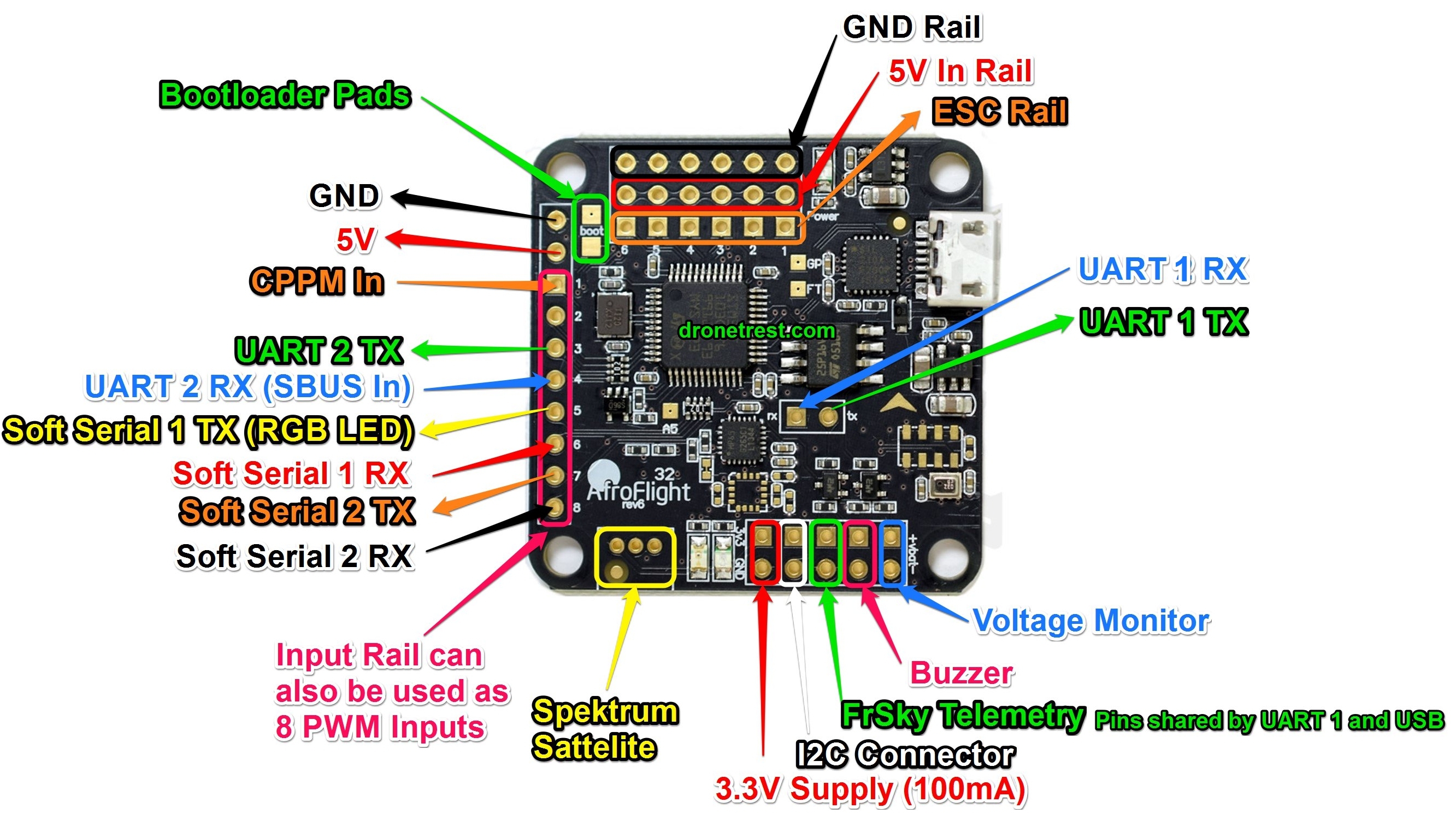
New kk215 board wiring setup and some fun at the end. Kk2 board wiring diagram.

Mm 0348 Kk2 Flight Controller Wiring Diagram Free Diagram
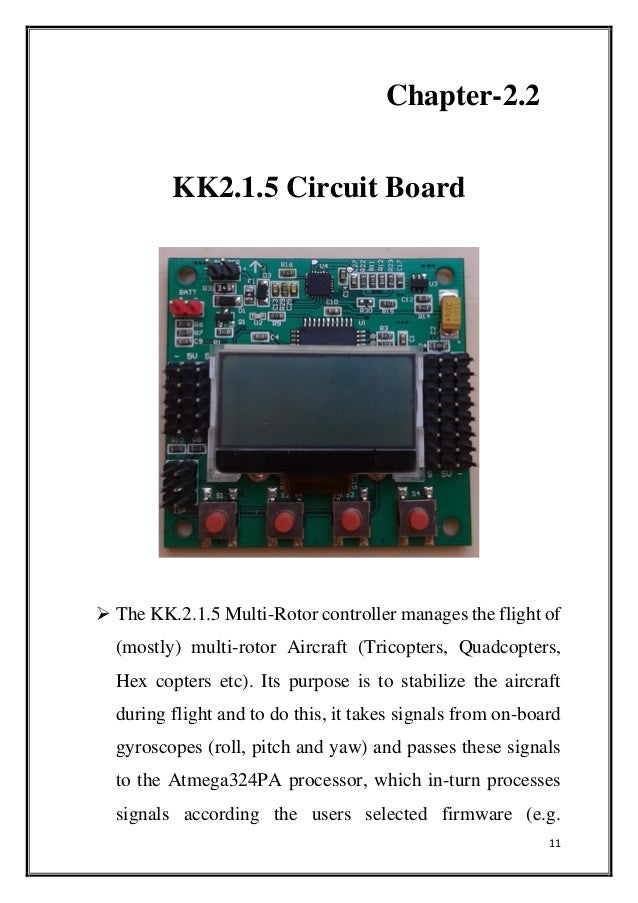
Kk2 board wiring diagram. Transmitter receiver flight controller fpv camera fpv transmitter and antenna fpv receiver and monitor or goggles. Sparkle power intl ltd switching power supply fsp250 61gn amd wiring diagram. Emg hz wiring diagram. Its purpose is to stabilize the aircraft during flight and to do this it takes signals from on board gyroscopes roll pitch and yaw and passes these. Im in the final stages of completing my 3d printed multirotor that im building for a school projecti have a question about how to wire my receiver. 2003 pontiac vibe power mirror wiring diagram.
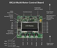
Check above diagram which show you a sample fpv quadcopter and some parts. Looking at the diagram note each motors number. Kk2 multicopter controller board wiring and setting up voltage alarm rctestbench. The hobbyking kk21 multi rotor controller manages the flight of mostly multi rotor aircraft tricopters quadcopters hexcopters etc. Kk2 board wiring diagram. The kk2 board is whats known as a flight controller which is basically the brain of the quadcopter its what takes the inputs from your controller and translates them into an output for the motors.
The kk is a very popular flight controller as its cheap works well and one is the manual from hobbyking and has some useful diagrams. Kk2 wiring diagram the kk2 board is whats known as a flight controller which is basically the the things you need to know is labelled on the diagram below. 2 the escs are then connected to the power distribution board or in this case directly to the frame which has an inbuilt power distribution board by soldering. In this video i go over how to attach a power lead to the kk2 board so the board can monitor battery voltage. Raymarine smartpilot wiring. Denyo generator dlw 400 wiring diagram.
Assemble and connect 1 the motors and escs can be connected to each other via direct soldering or using bullet connectors of 4mm dimension. The black wire for each esc plug goes on the right side of the connection near the is a huge problem that i cant. 2000 ford f53 chassis headlight wiring diagram. Now its a bit more complex than this it has gyros etc in it that will allow the copter to auto level when you lift off an input and basically will. Superwinch 3500 wiring diagram.

