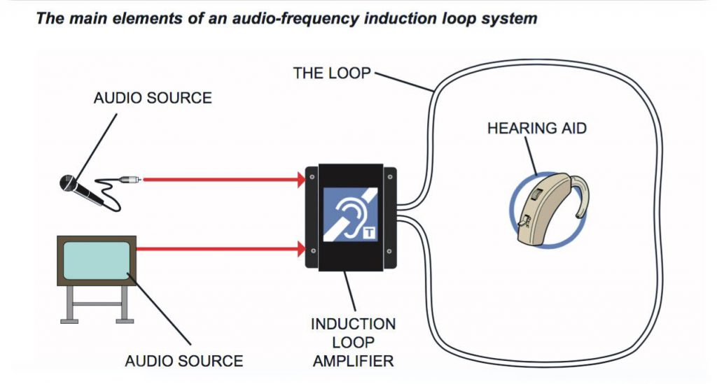
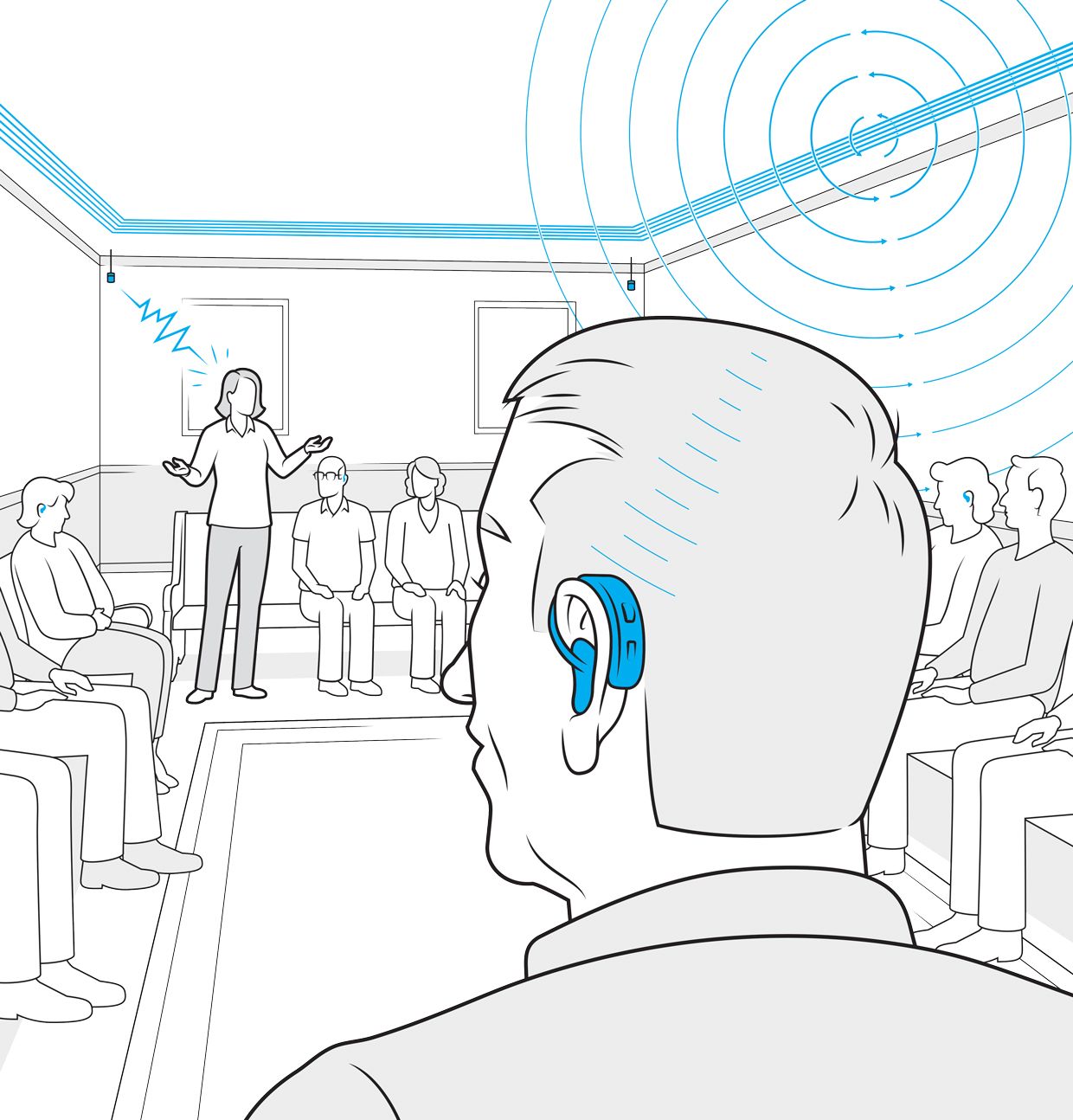
Place backer material into the saw cut over the loop wire and pack tightly. An induction loop system consists of one or more loops of wire driven by an amplifier to produce a magnetic field.

Hearing Loops For Small Areas Wayne Staab
Induction loop wiring diagram. Loop series marking sleeve loop number a b s sb fb sa s start fa f finish traffic flow junction box f b offset crimps splice typ a letter typ loop series typ 2csh cable marking sleeve typ loop number splice demand loops passage loop s sf traffic flow loop wiring diagram type r1 and r1w loop wiring diagram type r2 and r1wa. These fluctuations or magnetic waves are picked up by t coil equipped devices such as a. In the uk the installation of induction loop systems is governed by bs7594 the code of practice for audio frequency induction loop systems and en60118 4 magnetic field. What is an induction loop system. Place the loop into the saw cut. Notch out for the t connection where the lead wire connects to the loop.
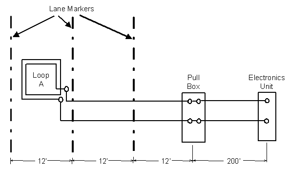
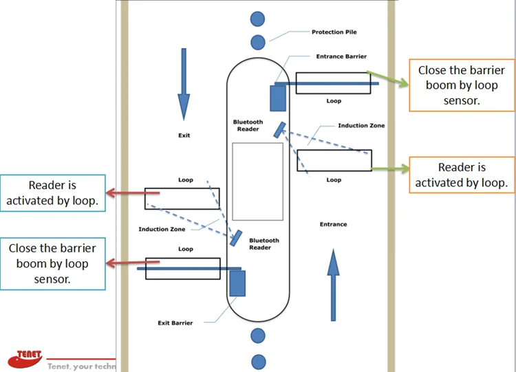
Induction loop systems aims to provide straightforward explanations of the technology involved together with hints tips and advice on best practice installation. An inductive loop is a wire wound in a rectangular square or round shape that is typically saw cut into the pavement. The best quality wire you should be using should be close to or around 14awg as higher gauge wire has less resistance and much stronger tensile strength. The ends of the wire are brought back to an enclosure which houses an inductive loop detector module. Loops should never have an air pocket within the loop because ground vibrations can cause false detections which results in repeat service calls. Place a high quality sealer over the saw cut to seal the surface.
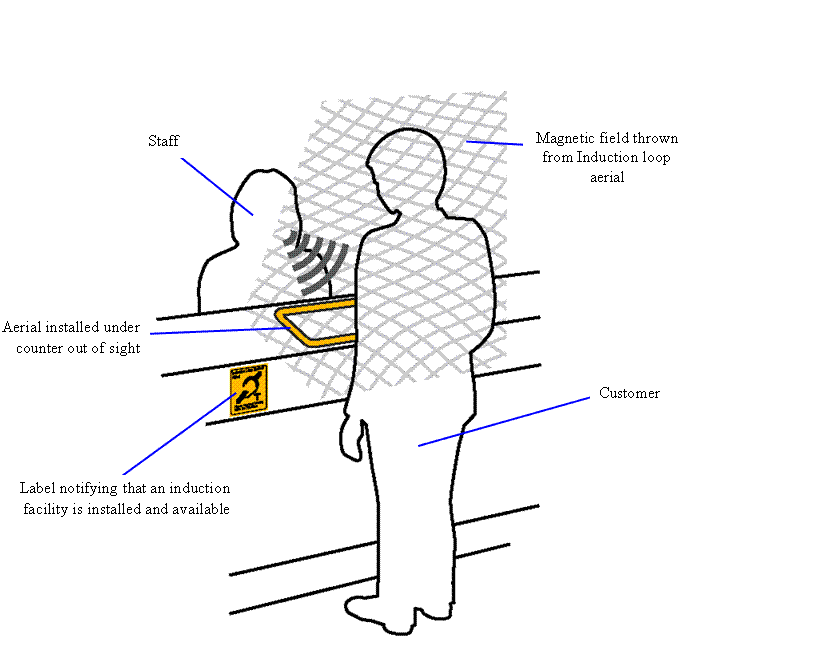
When audio is input into the amplifier this magnetic field fluctuates. Remove all debris from the finished cut with compressed air.

