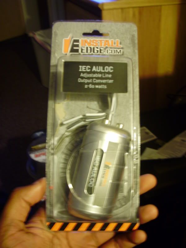
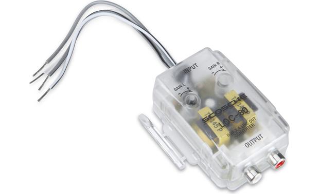
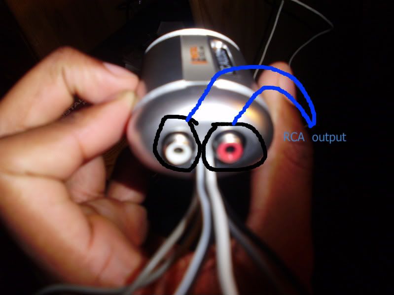
Im helping my son wire his 2000 durango with an install edge iec auloc line output converter. Need a new user manual or see installation process view manual here.
Need Help With My Diy Amp Amp Sub Install 8th Generation Honda
Iec auloc wiring diagram. Install edge iec auloc line output converter wiring total rookie here. Adjustable line output converter 2 50 watts. Iec auloc wiring diagram how to configure surround sound system for optimal sound modern technology has advanced to the point that some home system setups allow you to position a microphone where you plan to sit in the heart of your personal media temple then fire up an automatic program step out of the room and let your surrogate ear and. Iec auloc do i hook up the iec auloc to my car stereo posted in the12volts install bay car audio forum relay diagrams. He lost the wiring diagram is there anyway to find that on line or is anyone familiar with this item. Edge products installation manuals and user manuals.
Included in the iec chart are types of outlets inlet types pin spacing appliance class voltage amperage and more. M a1 a2 m. Scosche line out converter wiring diagram best of. Iec auloc wiring diagram need help figuering out this wiring diagram for stock radio audio converter i have is an iec auloc bough off ebay a couple months ago but. The purpose of this document is to provide a simple cross reference of common schematicwiring diagram symbols used throughout various parts of the world. When wiring so the 1 wire sensor is parasitic gnd and vdd are connected together and gnd is connected to the extension.
Scosche line out converter wiring diagram. Used for converting high level speaker line outputs from a source unit into low level rca jacks. This is a schematic diagram for connecting the one wire temperature sensor ds18b20. The pin assignments can vary between sensors so please refer to the manufacturers datasheet. Any user assumes the entire risk as to the accuracy and use of this information. The iec chart serves as a guide for proper plug identification.
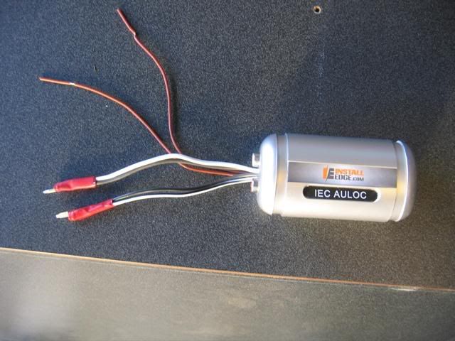
It has 2 sets of white and bl. Typical controller markings typical elementary diagram iec typical controller markings typical elementary diagram table 4 control and power connections for across the line starters 600 v or less from nema standard ics 2 321a60 1 phase 2 phase 4 wire 3 phase. Iec schematic diagrams general with the increasing emphasis on globalization many industries are now looking to all parts of the. Connect iec auloc white wire whiteblack to the left speaker output itll come up with a diagram that will tell you which wires do what.

