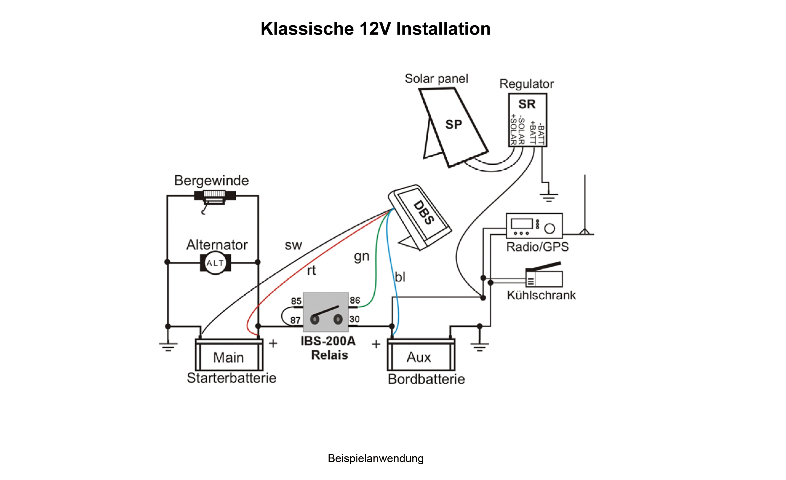
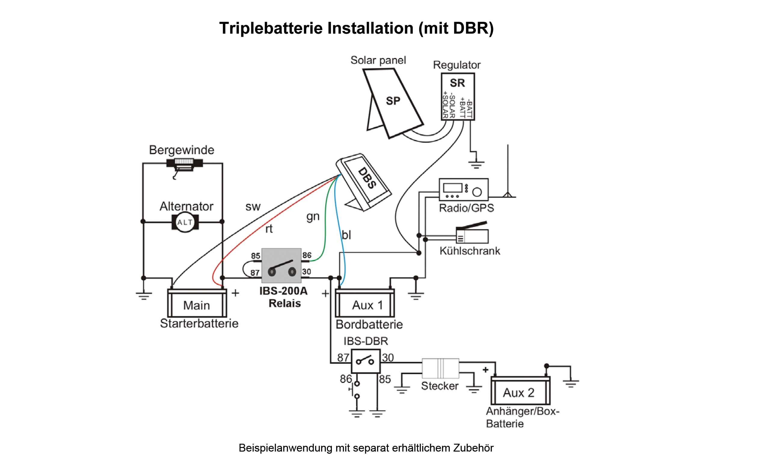
The green wire connects to terminal 86 on the ibs relay. The yellow wire connects to terminal 85 on the ibs relay.
Battery Sensor How It Works Problems Checking Battery
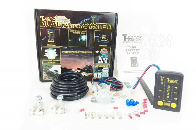
Ibs battery monitor wiring diagram. 41 33 221 06 16 fax. Designed to improve the functionality of the ibs dbs dual battery system ibs dbs and dbi dbs in the event that the starter battery is empty or fails totally. The ibs contains a micro processor that is used to monitormeasure various battery conditions such as. Ibs dual battery system with link deactivation if trailer battery is missing. An ibs is better able to monitor the batterys state of health than conventional sensing systems. Info at ibs techch ibs dbsenv110doc 1 ibs dbs dual battery system manual.
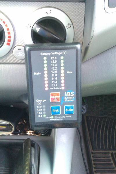
Renewable energy applications are another area in which ibs units excel. If the battery voltage to the starter battery main drops for a longer periods below 12v the red led and beep at a slow blink rate is present blinks at 2 sec interval. The following battery systems and monitors or displays are available. Trailer battery recognition disengages the automatic and manual link function if the aux battery has been removed. If the battery voltage at the aux battery is for a longer time under 12v the red led flash frequency with fast beep the blinking interval 6 seconds. Find schematics for your product.
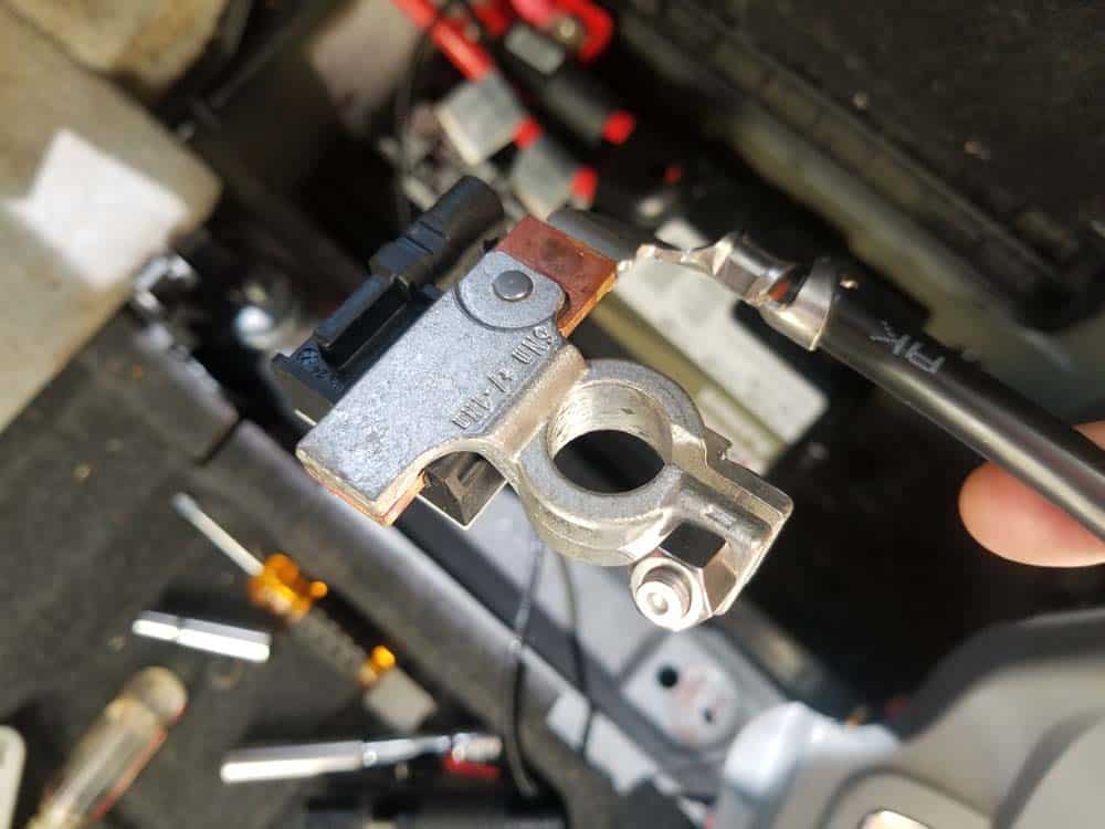
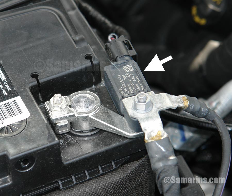
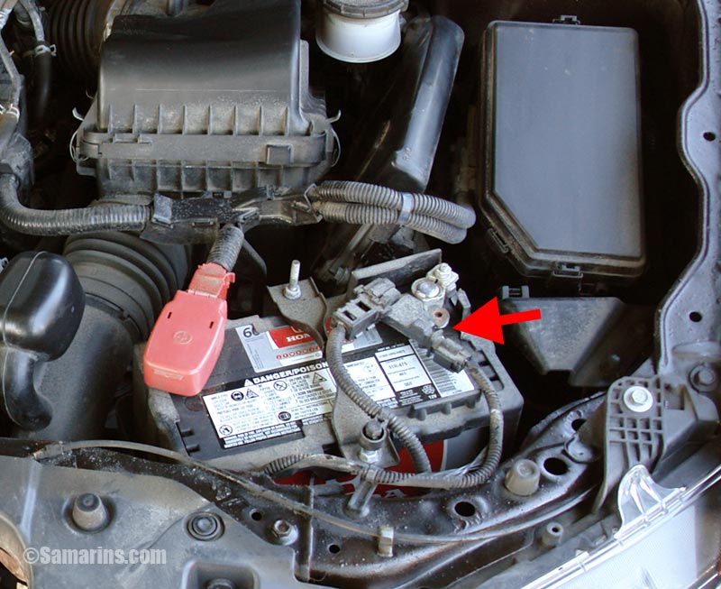
Terminal voltage via measurement from b to gnd chargedischarge current via. The first and most obvious area is anywhere a battery is charged by a renewable energy source and used as either a back up source or the full source such as off grid. The new software 8 with the new features is now available. Dual battery system with incarcharger function ibs dbr. The bmw intelligent battery sensor ibs is a mechanicalelectronic device which is connected directly to the negative battery terminal. The blue wire connects to terminal 30 on the ibs relay.
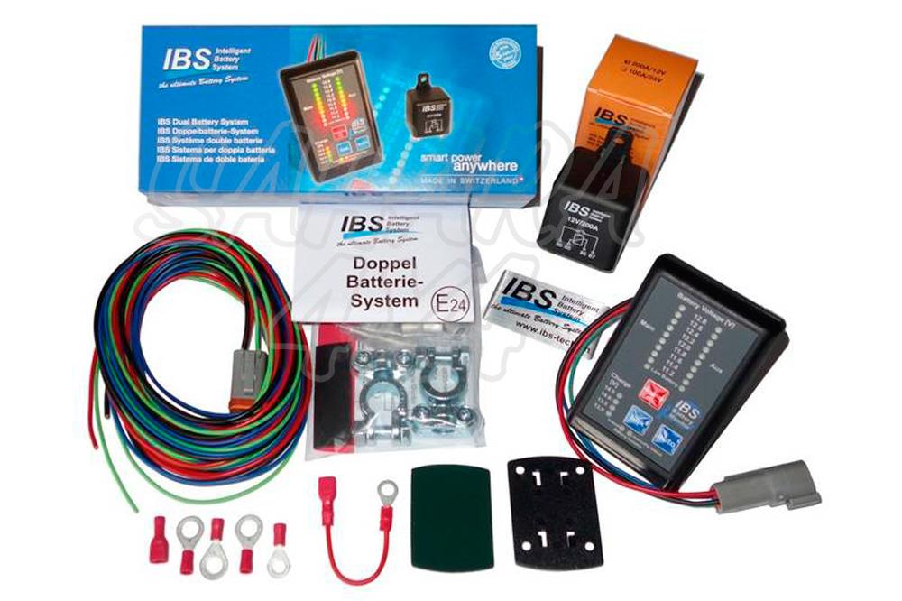
Ibs intelligent battery system gmbh seestrasse 24 ch 3600 thun schweiz tel. The red wire is connected to terminal 87 on the ibs relay. Dual battery packs simple and compact double battery system. Double battery system in 12v or 24v ibs rbm. Additional module for ibs dbs extended function at emergency start ibs dbm20a. The rbm booster module has four wires that will need to be connected to the ibs relay.
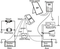
Connect an electrical recovery winch to the main battery as shown in the wiring diagram. A system schematic shows schematically how victron energy devices are connected to each other. An electrical recovery winch connected to the main battery is recommended to be installed as shown in the wiring diagram below. 41 33 221 06 17 e mail. Rbm relay booster module.

