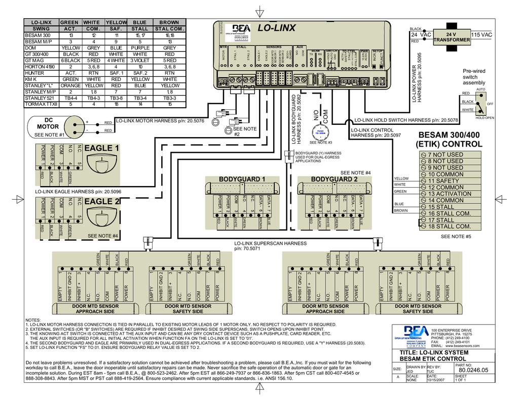
Horton automatics offers its 4000 series and 7000 series swing operators to provide a full range of swinging and folding access solutions. If there are any questions about these instructions call horton automatics technical assistance.

Bea Gyrotech 1100 User S Manual Manualzz
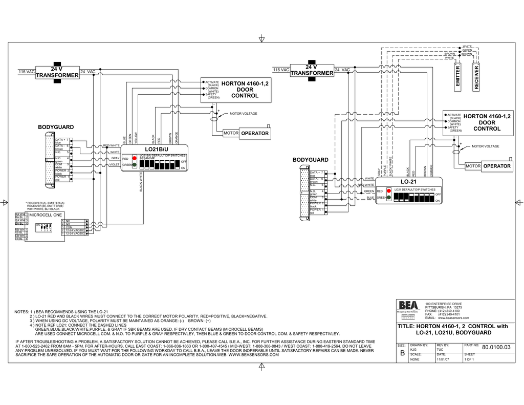
Horton 4100 series wiring diagram. Image part number description uom. Specify horton and demand aaadm certi ed installation. Information to be provided by the distributor to the owner gbif1 2. Sargent 7700 8100 schlage l series yale 8700 dorma m9080 premium trim skirt for the 4100 using the trim skirt the skirt can be used to clean up the cut line of the frame face during installation. 3 4 1 9 c. Extrupvc 1 nom id cylinder.
The rim sk ir tcomeswi h 2 screw fo as enng to the top and bottom of the 4100. Intensive care unit doors. Hurricane rated sliding doors. Manuals and user guides for bea horton c4190. Typical mounting and wiring for single unit side access shown general installation hd swing series 4100 typical mounting and rough in wiring t n o t e. Parts catalog part number.
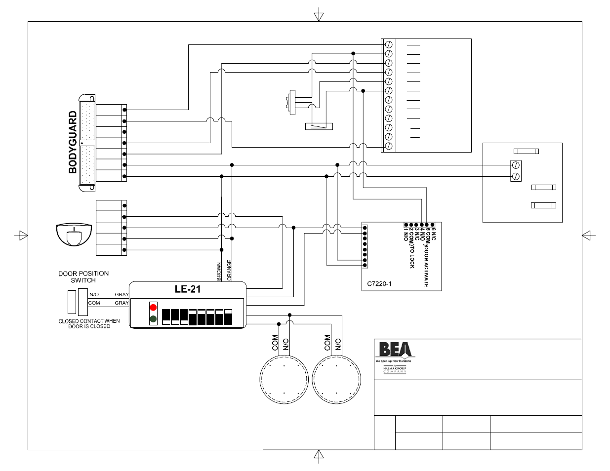
Drill f 257 clearance holes through backmember only. Wire the lock to a horton c3881 auxiliary relay module as per diagram 113806. Standard arm 4 12 114 series 4000 electric operator output shaft drill all holes 7 201 through backmember frame. Optional full access header for series 4100 inswing outswing b30. We have 1 bea horton c4190 manual available for free pdf download. Series 7100 swing mounting rough in wiring b12.
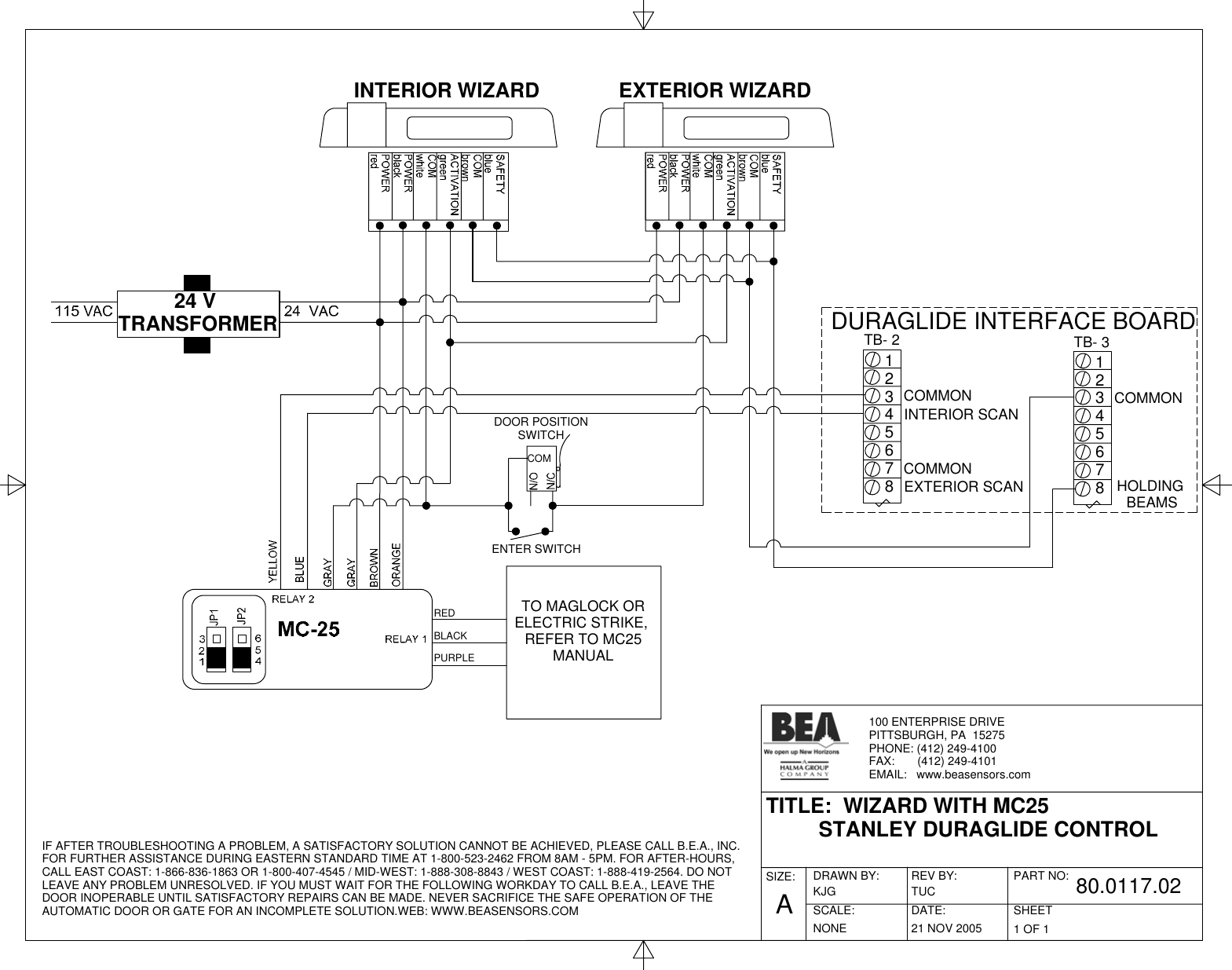
Wiring diagram bea horton c4190 wiring diagram 20 pages. Connect the c3881 to cn2 as shown. Push plate 60 1 52 4 32 812 minimum push button or 120 vac required 24 610 minimum alternate switch location series 4100 le operator access 6 152 4000le operator 6 1 52 driveb lock operator access powera rm 4000le operat or 4 12 114 6 1 52 exterior 8 203 6 1. To ensure safe and proper operation the door must be installed and adjusted to conform to horton automatics recommendations all code requirements and ansi a15610. 3rd step 06 07 05 4141d3 lock relay connections see wiring diagram jb4 place the jumper in any of the positions shown to archive the required lock delay 1 jb4 3 5 8 2 10 sec 75. Available in 6 architectual finishes.
P r op e r s u p p o r is r e q u i r e di n t h e e m o u n t i n g a r e a. Cycle the door and check for proper lock operaton. W d b l o c k i n g n w a l l b o a r i s r e c o m m e n d d. Hole locations will vary. Series 4100 bottom load series 4000 electric operator 6 316 157 exterior side 3419 inswing parallel arm 6 152 4081d access pnl.


