Gooseneck trailer hitch systems. Ny fl ca mi pa tx and ontario canada.

Trailer Wiring And Brake Control Wiring For Towing Trailers
Hitch wiring diagram. Below is the generic schematic of how the wiring goes. Home electrical wiring including diagrams wiring diagrams. It shows the elements of the circuit as simplified shapes as well as the power and signal links in between the devices. Fifth wheel trailer hitches. 4 pin trailer wiring diagram. April 13 2020 by larry a.
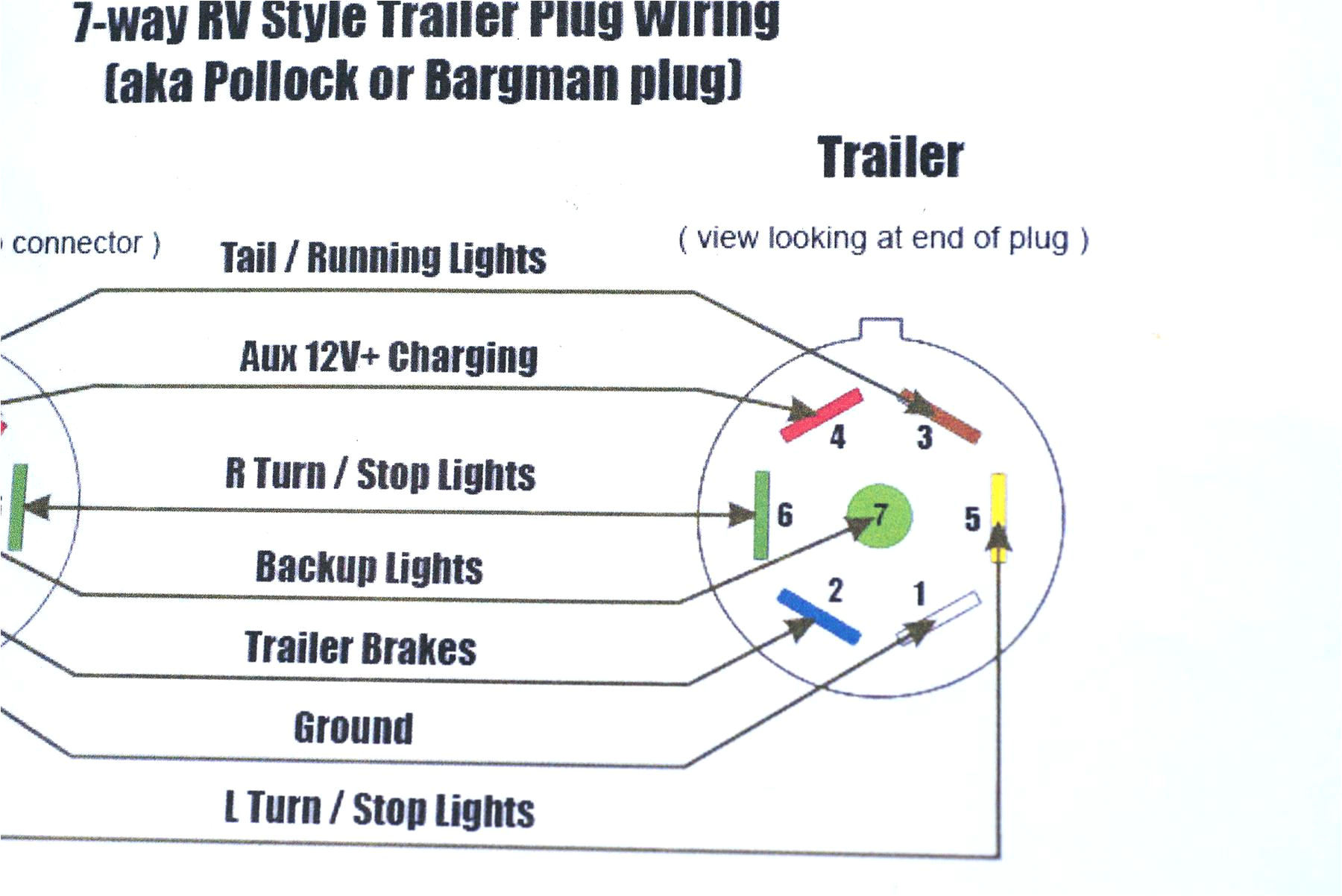
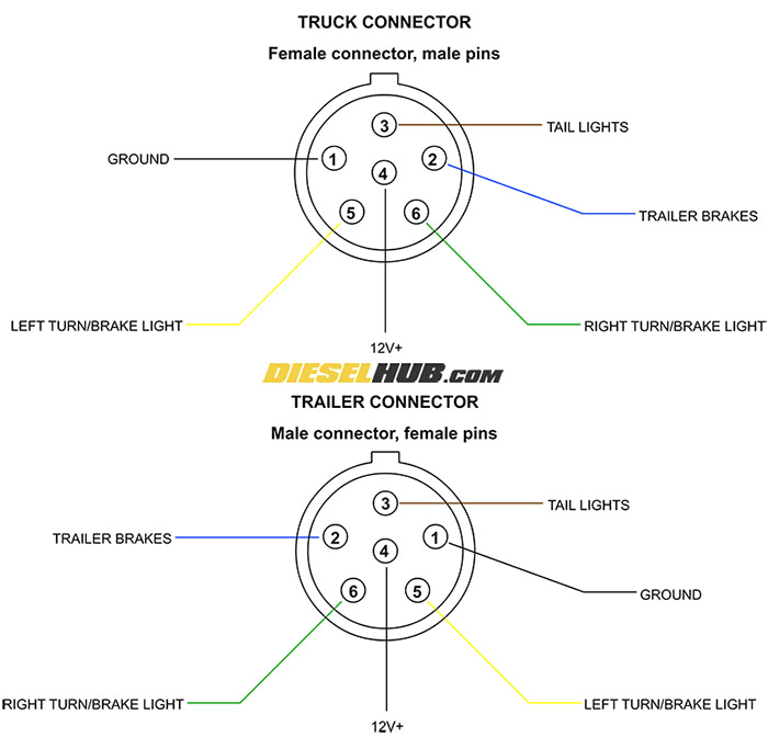
A wiring diagram is a streamlined standard photographic representation of an electric circuit. Front mount trailer hitches. Complete with a color coded trailer wiring diagram for each plug type this guide walks through various trailer wiring installation solution including custom wiring splice in wiring and replacement wiring. Variety of tow hitch wiring diagram. Above we have describes the main types of trailer wiring diagrams. In this case you will need a set of wiring taps and a pair of pliers.
If your vehicle is not equipped with a working trailer wiring harness there are a number of different solutions to provide the perfect fit for your specific vehicle. Tow hitch wiring diagram. Various connectors are available from four to seven pins that allow for the transfer of power for the lighting as well as auxiliary functions such as an electric trailer brake controller backup lights or a 12v power supply for a winch or interior trailer lights. Check out or trailer wiring diagrams for a quick reference on trailer wiring. To connect the electric system of your trailer to the vehicle you will be using special connector. 1 877 hitch it 448 2448 shipping locations.
The below information is for reference and is commonly used throughout the industry but can vary depending on who built the trailer. Trailer wiring diagrams trailer wiring connectors. You can use a circuit tester to verify connections.


