Supervised linear power supply with battery backup input surge protection and ac fail and battery low contact outputsseparate supervised dc supply with battery back up recommended for relay activated devices. Therefore you cannot unplug a connector from one side and plug it into the corresponding connector on the other side.
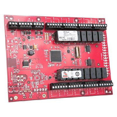
Hid Access Controllers Access Controller Systems
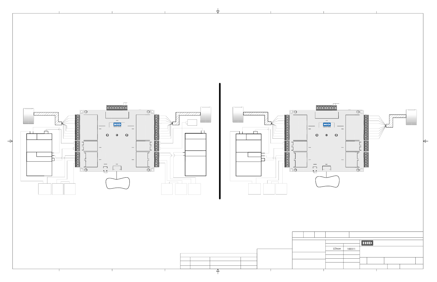
Hid vertx v100 wiring diagram. The vertx evo v1000 is a networked access controller with a multi door access control panel. This vertx installation wiring diagram is intended as an example only and should not be interpreted as an hid corporation recommendation. Hid globals vertx evo open platform is flexible and scalable to permit economic and high. 60 ma at 9 18 vdcrecommended. Master controller interfacing to vertx v100 v200 and v300 door and io interface devices. A4 34 wiring vertx evo warning.
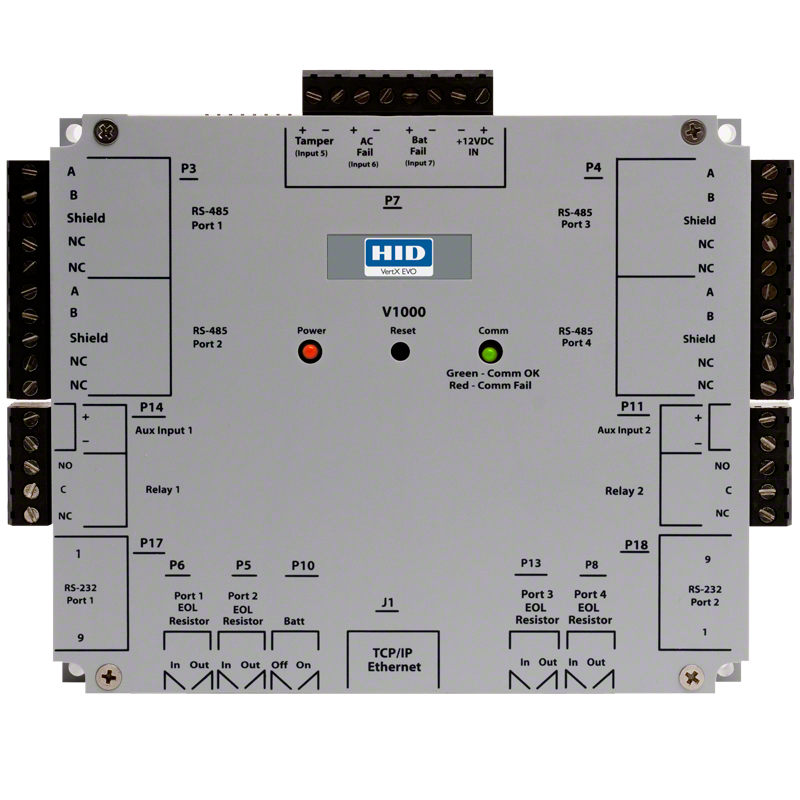
136 oz 38 kg power supply requirements. Vertx evo v1000 is a non poe device. The hid vertx evo v1000 intelligent controller is ip ready and minimizes bandwidth usage on an organizations network by connecting up to 20 downstream interface modules and 40 readers using a single ip address. Power and alarm input connections all vertx units. The hid vertx products provide a complete and fully featured hardwarefirmware infrastructure for access control software host systems. The vertx devices can be stacked with or without the cover.
Each rs 485 bus can support a maximum of 16 v100 series panels using one or two ports. Hid vertx evo v1000 networked controller. Connectors on the vertx devices are positioned to be mirror images and are not interchangeable once the installation is complete. Do not remove the plastic base. Do not connect j1 ethernet port to a poe capable port. Installation wiring diagram example 1 note.
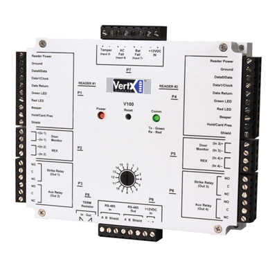
The v100 door reader interface connects two access control card readers via wiegand or clock and data interface controlling either one or two doors. 58 w x 4825 h x 1275 d 14732 mm x 12255 mm x 3238 mm weight. If the v100 series panel will be attached to the end of the rs 485 bus install a terminating jumper to the in. Make sure you position the vertx devices in such a way as to provide room for wiring air flow and cable runs. This applies to both direct poe power sourcing equipment endspan pse and poe injector midspan pse equipment. The v1000 physical rs 485 port 1 and 2 reside on logical bus 1 p3 while port 3 and 4 reside on rs 485 logical bus 2 p4.
14 v100 v200 or v300. Wiring vertx evo vertx evo v1000 user guide 71000 901 rev. The v1000 connects to downstream interface modules hid vertx v100 v200 v300 over rs 485 and handles all access control decisions. It reduces the burden on corporate local area networks lans by. 22 wiring vertx caution.

