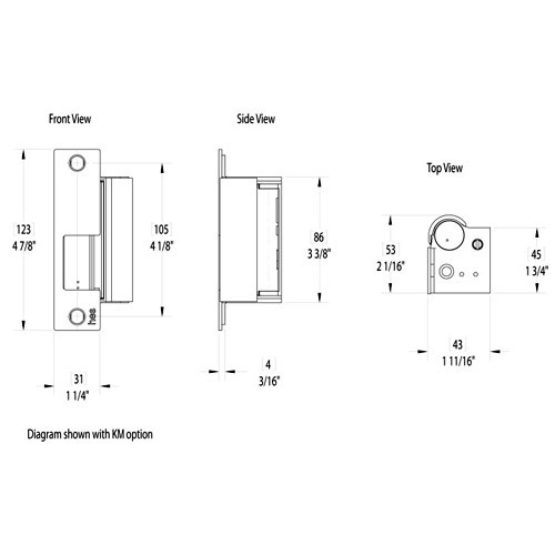
Hes 9400 9500 9600 surface mounted electric strikes video duration. Diagram shown with n option.
Hes Electric Strikes Wiring Diagram Axxess Tyto 01 Wiring
Hes 9400 wiring diagram. All components are completely encased within its 58 thick stainless steel housing so no cutting on the frame is required. 09102018 09102018 0 comments on hes 9400 wiring diagram. The innovation strength and service of hes harmonizing with the durability quality and no fault warranty of securitron. A wiring diagram is a simple visual depiction of the physical links and physical layout of an electric system or circuit. Do you have a question concerning hes but dont know who to contact. Jamb view the 4500 is the first strike designed for installation in 2 ul 10c fire rated frames with 12 drywall penetration 12383 4 78 7938 3 58 318 1 14 244 1 12 lbm wiring white orange normally open green normally closed common diagram 3.
For additional information consult hes customer support at 1 800 626 7590. Hes 9400 electric strike. If no connector is present then configure the wires as shown in diagram 2. Hes 12 24d wiring diagram a beginner s overview of circuit diagrams. The 9600 series is sold as a complete pre assembled model. Hes and securitron the worlds premier suppliers of electric strikes and access control components have united as assa abloy electronic security hardwarethis exciting combination accentuates the best of both brands.
Installation diagrams 3 diagram 7. Installation instructions. The 9400 series is a slim line surface mounted electric strike designed to accommodate rim exit devices with a 12 pullman latch. Hes 9400 wiring diagram. Faceplates accessories documents certifications listings. Jf series wiring door stations and power supply duration.
It demonstrates how the electric wires are adjoined and also could likewise reveal where components as well as parts could be linked to the system. Verifying the operation mode the hes 9400950096009700 electric strike is pre set for fail secure operation as shown in diagram 3. Page 2 then refer to diagrams 5 and 6 to neg redgreen complete wiring see page 3. Fail secure operation verify that both keepers are in fail secure operation. Latchbolt monitor diagram 4. New solutions include the fire rated series the slim line series and the iclass hybrid eliminate guesswork and confusing.
The 9400950096009700 ships in fail secure operation mode. Fail safe operation mode should not be used in. Summary of contents for assa abloy hes 9400 page 1 hes 940095009600 electric strike installation instructions and frame preparation product components diagram 1. If using the latchbolt monitor lbm or latchbolt strike monitor lbsm then refer to diagrams 3 and 4 on page 3 to complete wiring. Product components 940095009600 strike body 940095009600 cover 14 20 x 1 mounting screws 10 32 10 24 lockdown screws optional 6 32 x 14 cover screws 564 hex key 12.


