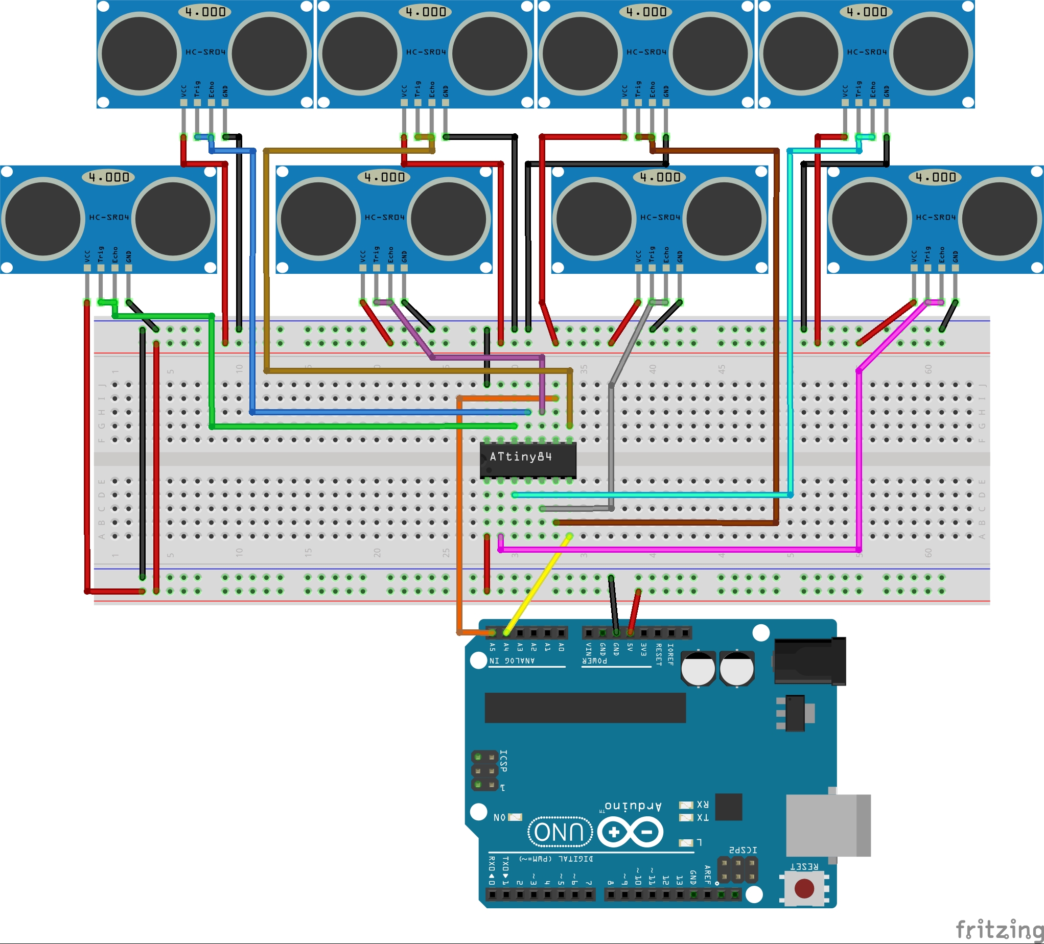
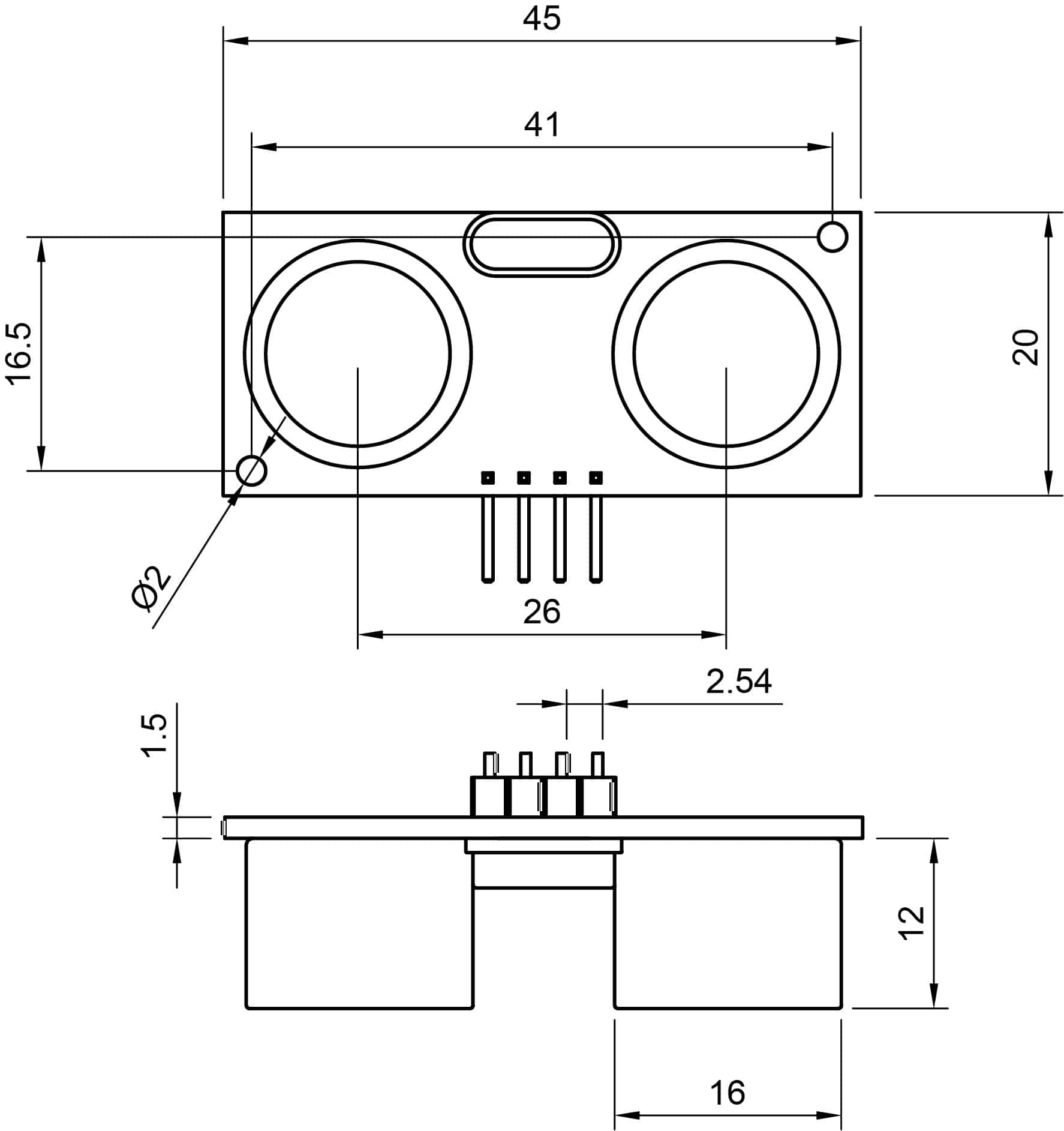
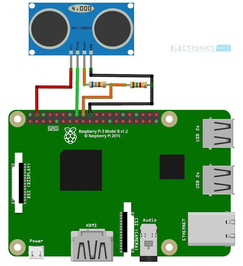
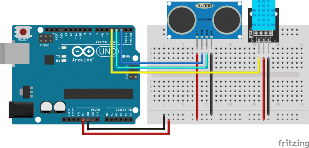
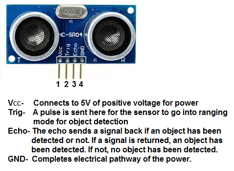
Hc sr04 ultrasonic sensor working as shown above the hc sr04 ultrasonic us sensor is a 4 pin module whose pin names are vcc trigger echo and ground respectively. The rest of the sketch is identical.
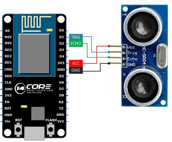
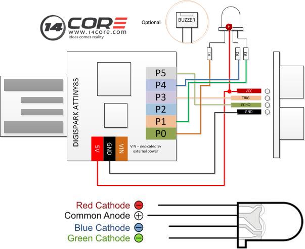
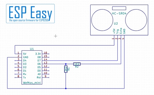
Wiring Esp8266 Nodemcu With Hcsr04 Ultrasonic Sensor 14core Com
Hc sr04 wiring diagram. Timing diagram the timing diagram is shown below. This sensor is used to measure the accurate distance between the target and the sensor. Ultrasonic hc sr04 timing diagram for example if the object is 20 cm away from the sensor and the speed of the sound is 340 ms or 0034 cmµs the sound wave will need to travel about 588 microseconds. The wiring diagramschematic below shows you how to connect the jsn sr04t sensor to the arduino. Sources for downloading hc sr04 pdf datasheet. It displays both the temperature the speed of sound and the measured distance on the lcd.
Hc sr04 is an ultrasonic ranging module that provides 2 cm to 400 cm non contact measurement function. You only need to supply a short 10us pulse to the trigger input to start the ranging and then the module will send out an 8 cycle burst of ultrasound at 40 khz and raise its echo. Ultrasonic ranging module hc sr04. The ranging accuracy can reach to 3mm and effectual angle is. Hc sr04 arduino wiring to thank you for visiting our site this is images about hc sr04 arduino wiring to posted by maria rodriquez in hc category on oct 14 2019you can also find other images like images wiring diagram images parts diagram images replacement parts images electrical diagram images repair manuals images engine diagram images engine scheme images wiring harness. Hc sr04 ultrasonic sensor working.
This sensor is a very popular sensor used in many applications where measuring distance or sensing objects are required. Hc sr04 with arduino dht11 and i2c lcd wiring diagram. The echo is a. It can be powered from a 5v power supply. The hc sr04 ultrasonic sensor comes with four pins namely vcc pin trigger pin echo pin ground pin. The breakout board of the jsn sr04t has the exact same pinout as the hc sr04 so it can be used as a drop in replacement.
Wiring diagram this diagram composed of arduino and hc sr04 ultrasonic ranging sensor and a buzzer with resistance of 330 ohms to limit the current. The cable of the sensor itself can be plugged into the connector on the back of the breakout board. The code below can be used to combine all 3 examples above. Wiring hc sr04 ultrasonic sensor to arduino uno 3 wire mode as you can see all you need to do is connect both the trigger and echo to arduino pin 9note that the only difference you need to do in the sketch is to define pin 9 for both the trigger and echo pin values. This sensor mostly works on the sound waves. The tone normally used to produce sounds with arduino shows conflict with the library ultrasonic also used in this project.

