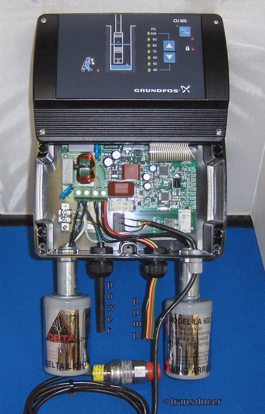
21 wiring diagrams and signal terminals and installation and operating instructions for mge 160 and mge 180. Assortment of grundfos circulating pump wiring diagram.

13e88 Grundfos Pump Motor Wiring Diagrams Wiring Resources
Grundfos wiring diagram. English gb 6 332 wiring diagrams fig. Our sp and sq pumps feature state of the art hydraulic design. Find installation and operation manuals now. 2 connection of 037 075 kw sa csir models tm06 5330 4615 tm06 5331 4615 control brw blk gry box fused switch brown yellow and green black grey use dotted line. Startup 17 111 general startup procedure 17 112 direction of rotation 17 12. A global leader in submersible ground water pumps grundfos has perfected the total package.
Wiring diagrams 18 131 symbols used in the wiring diagrams 18. If a certified wiring diagram is required for construction purposes please contact your local grundfos representative and a certified wiring diagram can be provided. Get your wiring diagrams. The cmbe series is available in both 1x110 120v and 1x200 240v variants and uses energy efficient permanent magnet motor technology which provides unmatched reliability quiet operation and energy savings. Page 1 grundfos instructions mge model f service instructions. It shows the elements of the circuit as streamlined forms as well as the power and signal links between the tools.
Grundfos submersible well pumps are available in a wide range of sizes and materials to fit your application needs. A wiring diagram is a simplified standard photographic representation of an electrical circuit. Go to grundfos product center. The seg range of grinder pumps from grundfos is specifically designed for pumping effluent and untreated sewage in small communities or sparsely populated areas with no sewer systems or where gravitation systems are unsuitable. The cmbe booster is designed for domestic and commercial water supply pressure boosting irrigation and dewatering applications. 101 servicing grundfos pumps with explosion proof motors 9 102 general information 9 103 changing the oil 10 104 dismantling the pump 10 105 assembling the pump 13 11.
Adjoining wire paths could be revealed about where particular receptacles or fixtures have to be on a typical circuit. Check that terminals 2 and 3 are connected and that the mge f has been started via the control panel. At the grundfos product center you can quickly and easily find pump installation guides pump manuals and all the technical data you need to keep your system working its best. These wiring diagrams are intended for general layout purposes only. Grundfos pump wiring diagram download building wiring representations reveal the approximate areas and affiliations of receptacles lights and long term electrical solutions in a structure. Literature general brochure product flyer data booklet installation operation guide wiring diagram.
1 overview of single phase connection for grundfos 3 wire control boxes fig. Fault finding 17 13.


