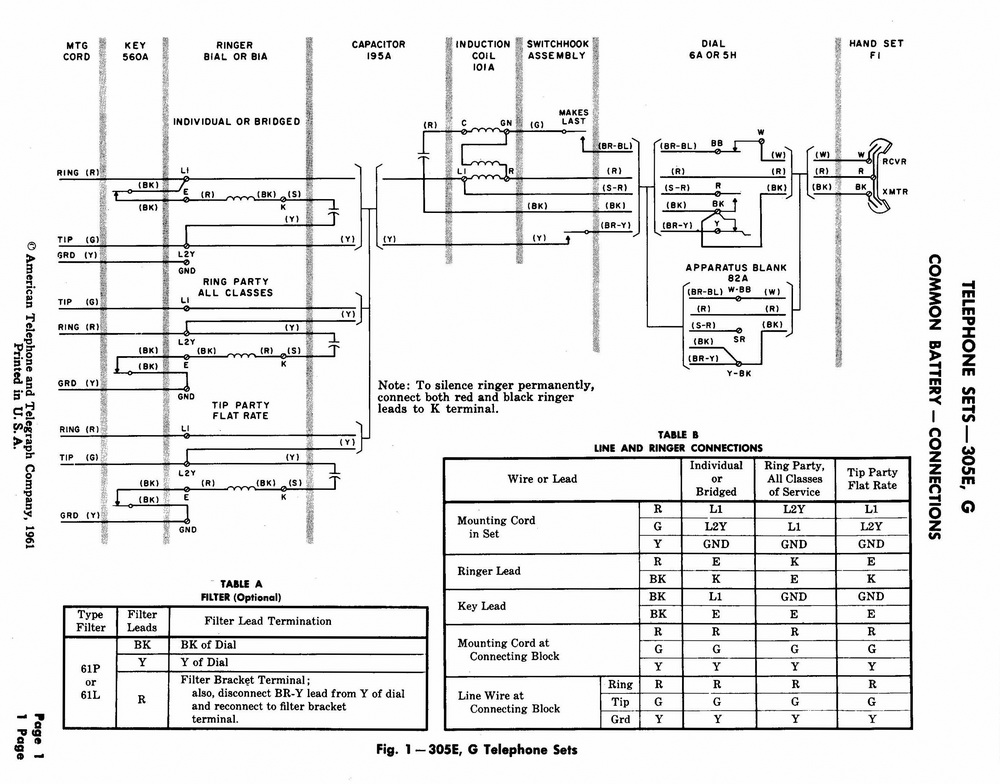
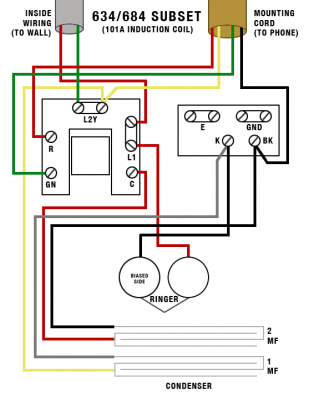
The full range of subscribers apparatus was covered. Connect white of line cord to b8.
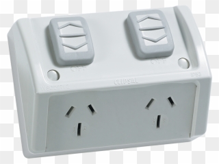
Socket Outlets Or Gpos Power Points Build
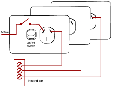
Gpo wiring diagram. Diagram for additional buttons n849. The term gpo is used in america and therefore appears quite a lot online but the terms outdated throughout the rest of the world. The extra switch is not colour coded like the gpo but one terminal has an l one a c and the other a 1. Weve whipped up a simple graphical raspberry pi gpio pinout. Not sure if this means anything or if it even matters as long as i. Connect red of line cord to b6.
Post office diagrams n q tg and sa. N diagrams were used by post office technicians when installing or servicing instruments and small systems. General information and links. Physical number corresponding to the pins physical location on the header. Bevins builds 11301 views. Is now available on a separate pagetoo.
B8 wired to t8. Telephone no 232 and 1232for use with bell set no 26 on cb auto systems on direct exchange lines etc. Wiring up a outlet tips and tricks. Wiringpi wiring pi pin number shown as a tooltip for gordon hendersons wiring pi library. Rev 1 pi alternate bcm numbers for the original 26 pin model a and b pi. I have moved the telephone wiring diagramsto their own page.
I want to wire a double gpo that has an extra switch to isolate mwave gpo i assume i would just loop piggyback the wires from the back of th gpo to the extra switch then run the wire to the mwave point as normal. B bellset terminal t telephone terminal. The general information on telephone dialing standards etc. Connect blue of line cord to be. B1 wired to t9. The standard diagram for the phone is n326 and the wiring diagram for the phone and bellset no.
Installing a wall plate with a c clip into gyprok or plasterboard duration. Socket outlets are available in many different styles and can only be installed or maintained by an electrician. See n4300 for connections. Index of files a script generating an index of folders and links to the actual n diagrams q diagrams and tg diagrams. Telephone is wired as follows. Alphabetical list of diagrams.
The printed wiring board is located by mating slots in the front edge of the board and in the sides of the plunger mounting bracket. Diagram for the auxiliary switches n848.


