Globe installation diagrams gl series residential pendent and never attach wiring ropes or fixtures to sprinkler or sprinkler piping. General description the globe models glr300g and glr300w ductile iron butterfly valves are indicating type valves designed and list ed for use in fire protection systems.

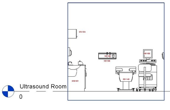
Pressure Switch Revit Family
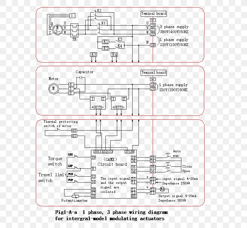
Globe glr300g wiring diagram. Butterfly valves with actuator. These valves are rated for a maximum working pressure of 300 psi 20 bar and provide a visual indication as to whether the valve is open or closed. These valves are rated for a maximum working pressure of 300 psi 20 bar and provide a visual indication as to whether the valve is open or closed. 2 12 3 4 6 8 globe model glr300g ductile iron grooved end butterfly valves are indicating type valves designed and listed for use in fire protection systems. 1 14 1 12 2 2 ½ globe model gl300g bronze butterfly valves groove groove are indicating type valves designed and listed for use in fire protection systems. Glrg grooved butterfly valves grooved end sizes.
Model vsr m flow switch typical wiring diagram flow switch requirements the model um floor control assembly is sold inclusive of. These valves are rated for a maximum working pressure of 300 psi 20 bar and provide a visual indication as to whether the valve is open or closed. 03102018 03102018 2 comments on globe glr300g wiring diagram. Bo g bo w butterfly valves are intended for indoor outdoor use. Globe glr300g wiring diagram. The globe series um universal manifold is a listedap.
Globe glr300g wiring diagram. The globe series um universal manifold is a listedap proved manifold. 4 the globe grooved butterfly valve should be connected to the globe butterfly valves are provided with internal supervisory. 1651 mm glr300g g x g 2 317735 d a b 890 404 1651 mm none g x g 2 317735 d a 445 202. 2 ½ 65mm 3 4 6.


