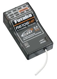
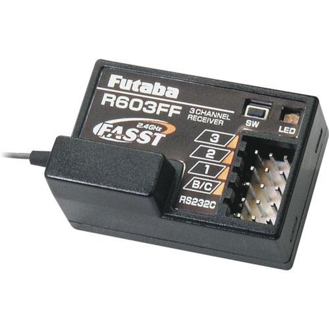
High sensitivity receiver weighs only 25oz 7g without case yet is a full range system for all aircraft from giant scale to park flyer applications no need to buy separate receiver for. Pay attention when connecting the usb wire.
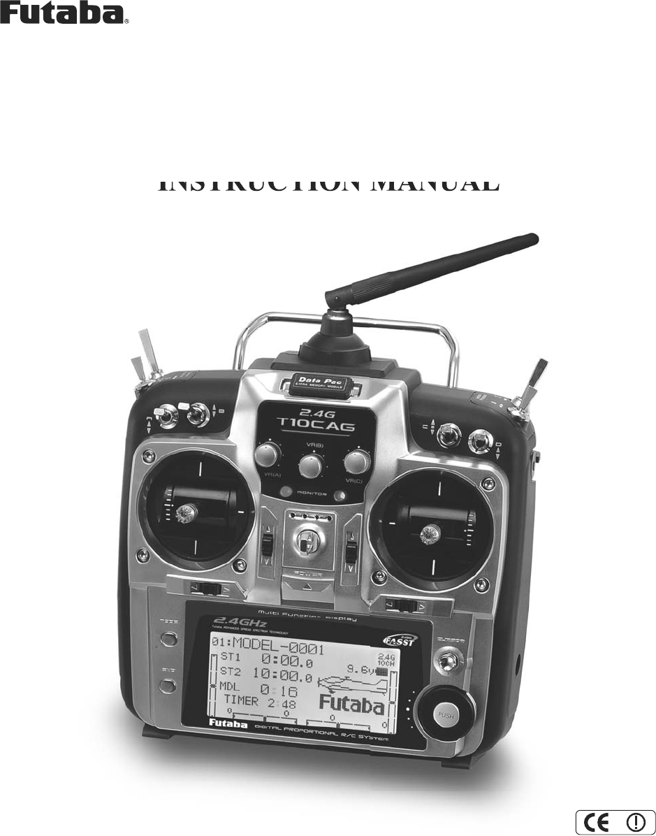
Futaba T10cg 24g Radio Control Transmitter User Manual 10cg
Futaba r617fs wiring diagram. I think i should be using the wiring diagram for the standard receiver but im not sure. 3 swashplate servos rx a not used rx b esc signal output rx c rx signal input rx 1 not used rx 2. It looks like the fasst setup in the manual is for the sbus type receivers but again this is a rookie. Im using an r617fs rx with the mini vbar. For futaba hitec and jr radio the servo and battery connections have the right polarity and signal wires although the connectors are physically different. 1m23n21301 futaba corporation 2008 03 1 r617fs 7 channel receiver of fasst system futaba r617fs 7 channel receiver of fasst system is packed in this set.
As long as you are careful about polarity. On page 20 of the manual it shows two options for placing the esc. In futaba hitec and jr radio servos the servo and battery connections have the same polarity and signal wiring although the connectors are slightly different. The two antennas should be placed at 90 degrees to each other. Wiring your mini vbar. You can mix futaba servos with an airtronics receiver mix hitec jr servos with a futaba receiver etc.
I am a complete vbar newb and cant figure out which wiring diagram in the manual i should be using. Receiver overview linking fasst receiver to futaba 14sg linking fasstest receiver to futaba 14sg r7008sb modes. Do not short circuit the connector for the control panelbluetooth module. You can mix futaba servos with an airtronics receiver mix hitec jr servos with a futaba receiver etc. Graupner hott and futaba s bus as well as multiplex m link. This is the futaba r617fs 24ghz fasst 7 channel park flyer to giant scale aircraft receiver.
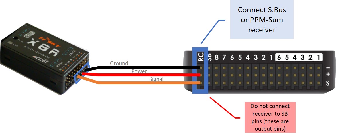
The main purpose of the photo demonstrates how the antenna should be placed. I went with option 2 placing the esc on the side of the frame. The image below shows the wiring diagram for my trex500 with a futaba r617fs 7channel receiver and a jr g7703d gyro. Somewhere along the line the wiring didnt become compatible. Rd tail rotor servo ch1. Click on the diagram to go full screen step 32 esc placement.


