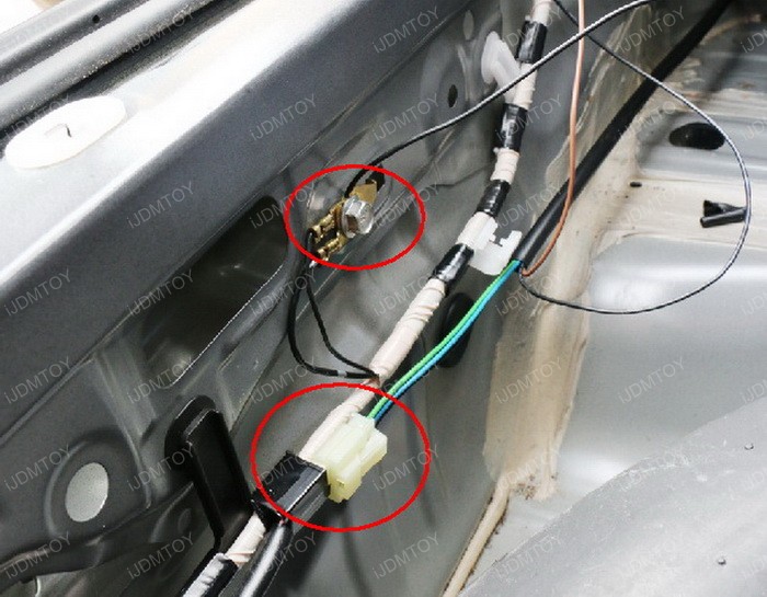
Here is how i wired up my spec d headlights. 1measure the lenght of the wire you need from the stock wiring going to the left to right if your battery is in the right then your wiring should start in right headlamp going to left.
Headlight Wiring Diagram Needed Tacoma World
Frs headlight wiring diagram. I definitely could have explained it better but thank you for bearing with me and. If you have two headlight relays you can choose either one. Refer to your vehicles wiring diagram and determine the color of wire and pin number of the power supply wire for your existing high beam headlights. First study the 3 diagrams that you will use as your guide on how you want to built your wiring. Assortment of chevy headlight switch wiring diagram. Remove the wire from the wiring harness.
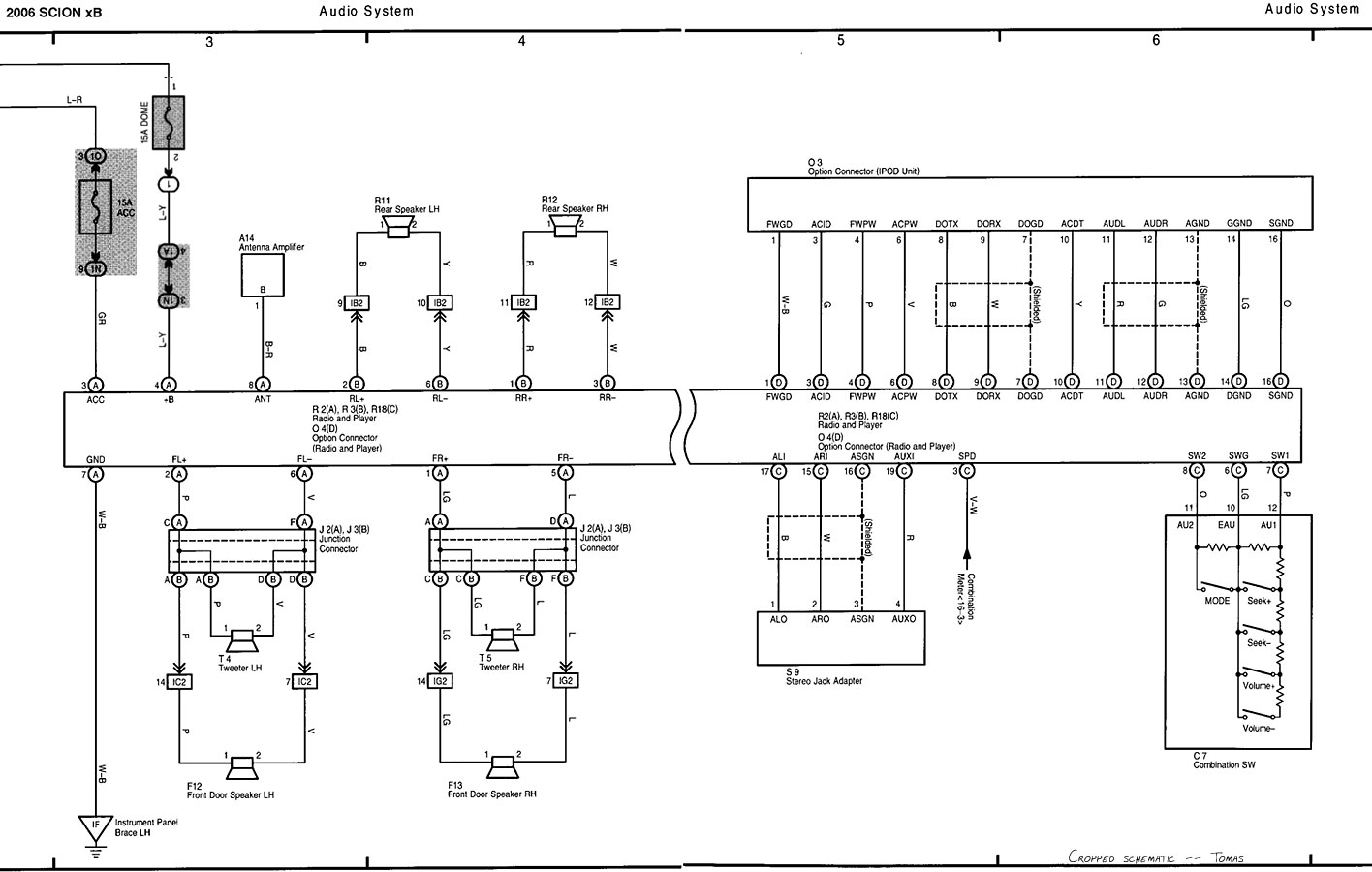
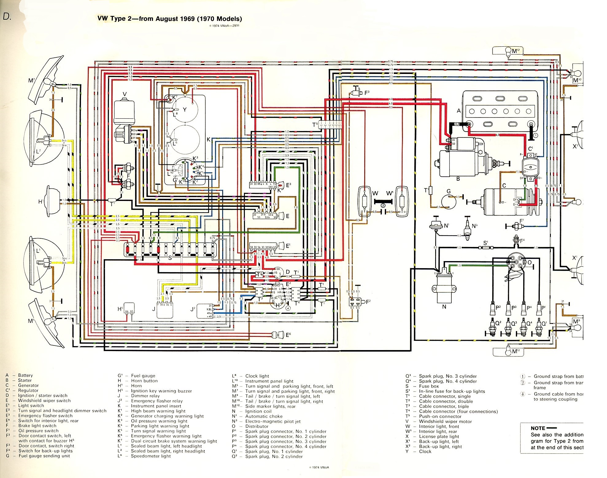
Whether your an expert scion frs mobile electronics installer scion frs fanatic or a novice scion frs enthusiast with a 2013 scion frs a car stereo wiring diagram can save yourself a lot of time. Official 2013 scion fr s subaru brz electrical wiring diagram diy do it yourself guides official 2013 scion fr s subaru brz electrical wiring diagram toyota gr86 86 fr s and subaru brz forum ft86club. This is for the drl to always be on when the key is in the ignition. Assortment of headlight dimmer switch wiring diagram. Look into the connector end of the wiring harness. It reveals the components of the circuit as simplified shapes and the power and also signal connections between the devices.
Automotive wiring in a 2013 scion frs vehicles are becoming increasing more difficult to identify due to the installation of more advanced factory. After you have all the things and tools you will use now lets make a headlight wiring relay kit. A wiring diagram is a streamlined traditional pictorial depiction of an electric circuit. Toyota avalon avensis aygo camry carina 2 corolla corona fj40 hiace hilux land cruiser prius rav4 supra tundra yaris electrical wiring diagrams. Ac air conditioning at automatic transmission abs anti lock brake system. A wiring diagram is a simplified conventional pictorial representation of an electric circuit.
It reveals the components of the circuit as simplified forms as well as the power and signal connections in between the devices. Abbreviations the following abbreviations are used in this manual.


