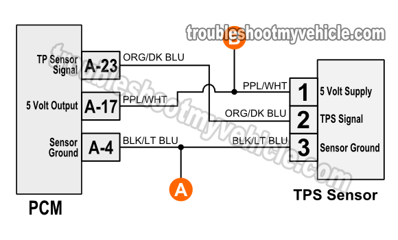
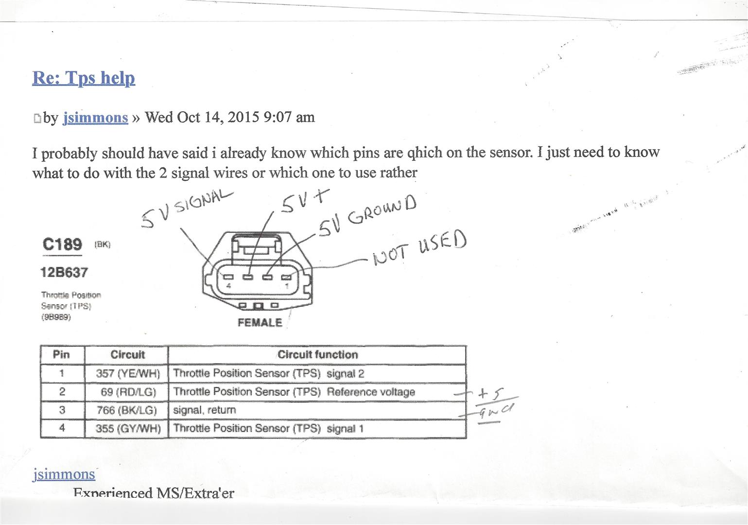
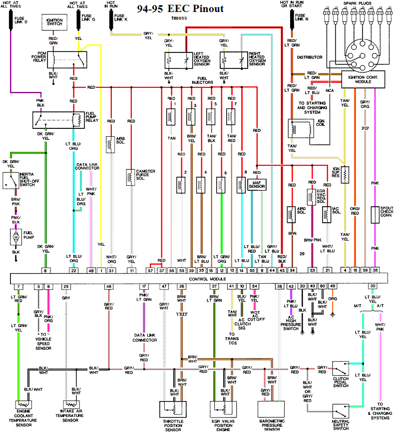
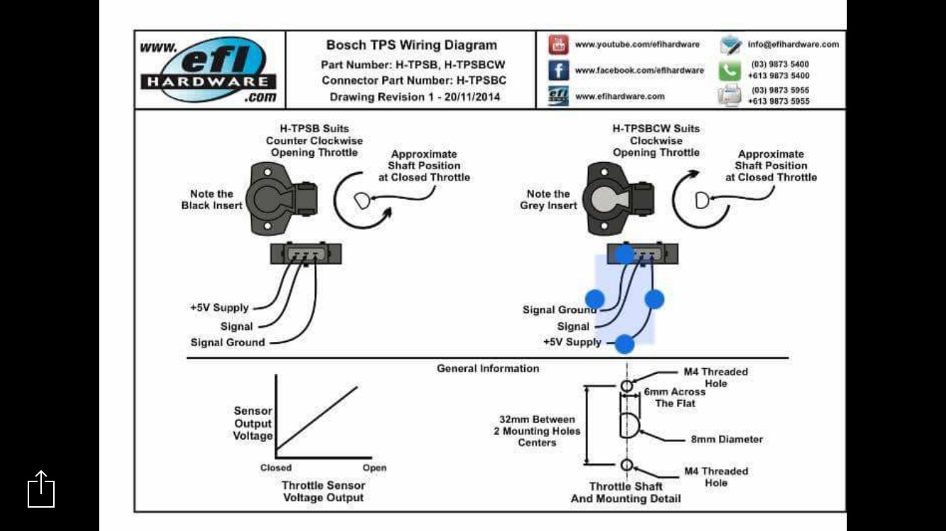
Brnwht wires feeds the tps 5 volts dc. Choose top quality brands delphi dorman forecast motorcraft standard motor products walker.

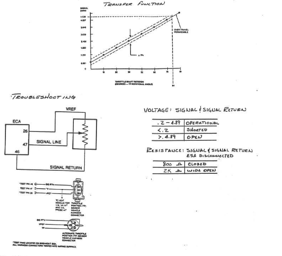
Part 1 How To Test The Tps With A Multimeter 1994 1995 3 8l
Ford tps wiring diagram. Ford vehicles diagrams schematics and service manuals download for free. A wiring diagram is a streamlined conventional pictorial depiction of an electric circuit. Throttle position sensor tps wiring diagram 1997 1998 ford 46l 54l. The gryred wire feeds ground. Buy a ford f throttle position sensor at discount prices. Variety of ford f150 wiring diagram.
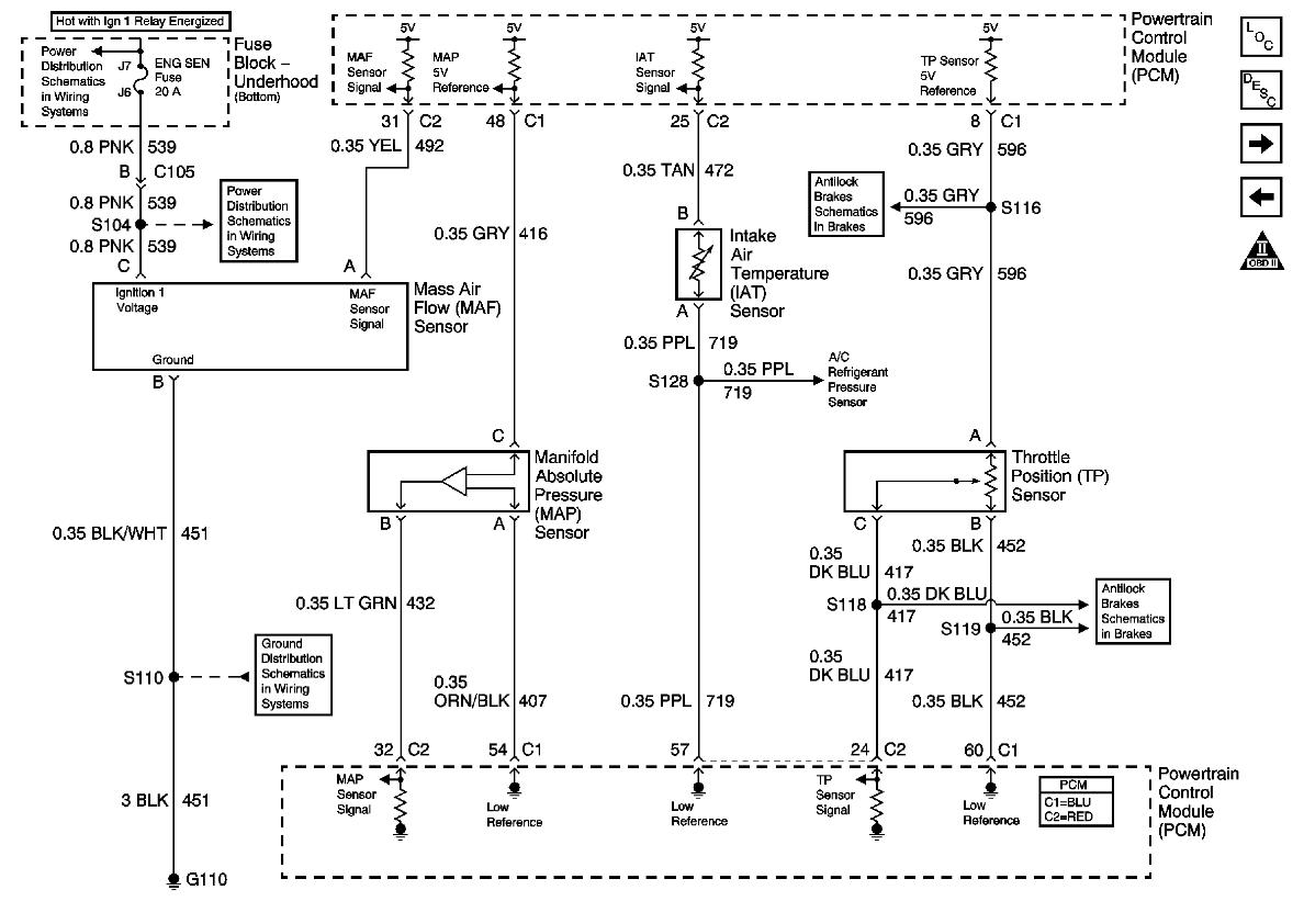
Ford forum is a community to discuss all things ford. For whatever reason ive been unable to upload the image after they lost it it keeps on telling me upload failed without giving me a reason whywhoaa. Throttle position sensor wiring diagram dodge throttle position sensor wiring diagram ford throttle position sensor wiring diagram gm throttle position sensor wiring diagram every electric structure is composed of various different components. Apr 07 can you please send me the wiring diagram for a ford f xlt with airconditioning and power windows and doors. Holley tps sensor connector. Ok if all of the above check out ok then your next step is to make check the continuity of the throttle position sensors wires between the pcm connector and the tps connector.
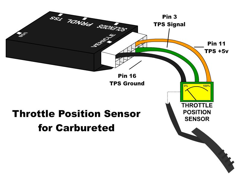
Otherwise the arrangement wont work as it ought to be. Ford throttle position sensor connections ford has two different color codes for throttle position sensors and several different connectors and pin outs. Ford s max 2006 electrical wiring diagramrar. I dont know how your ford tps sensor is wired. This is how the holley efi tps sensor is wired. 1957 ford thunderbird wiring diagram 1960 ford falcon 6 cylinder wiring diagram 1960 ford thunderbird v8 1962 ford galaxie v8 wiring diagram 1964 mustang master wiring locator diagram 1965 ford thunderbird convertible tops control diagram 1965 ford thunderbird window controls diagram 1965 mustang.
The grywht wire carries the tp signal to the pcm. It shows the components of the circuit as simplified forms and also the power and also signal links between the tools. Black is ground and should be tapped into the black. Ford sierra wiring diagrampdf. For all of you who have pm me asking for the tps wiring modification diagram. Orange wire 5v reference blackwhite wire ground green wire signal center terminal on both style connectors cavity a1 b2 c3 zoom in on the wiring diagrams in section 13 and look at the wiring configuration.
The following article has a simplified wiring diagram that may also be of help. F150 f250 f350 crown victoria e150 e250 e350. Check out our discussions on the ford escape mustang. Tp sensor wiring diagram 1997 1999 ford 46l 54l. The early style color code mostly matches the wiring of our harnesses. Each part ought to be placed and linked to different parts in particular manner.
Ford orion 1990 1999 electrical wiring diagrampdf.


