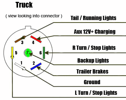
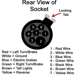
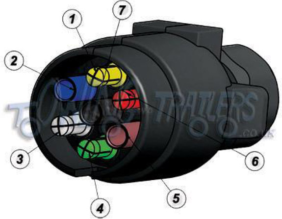
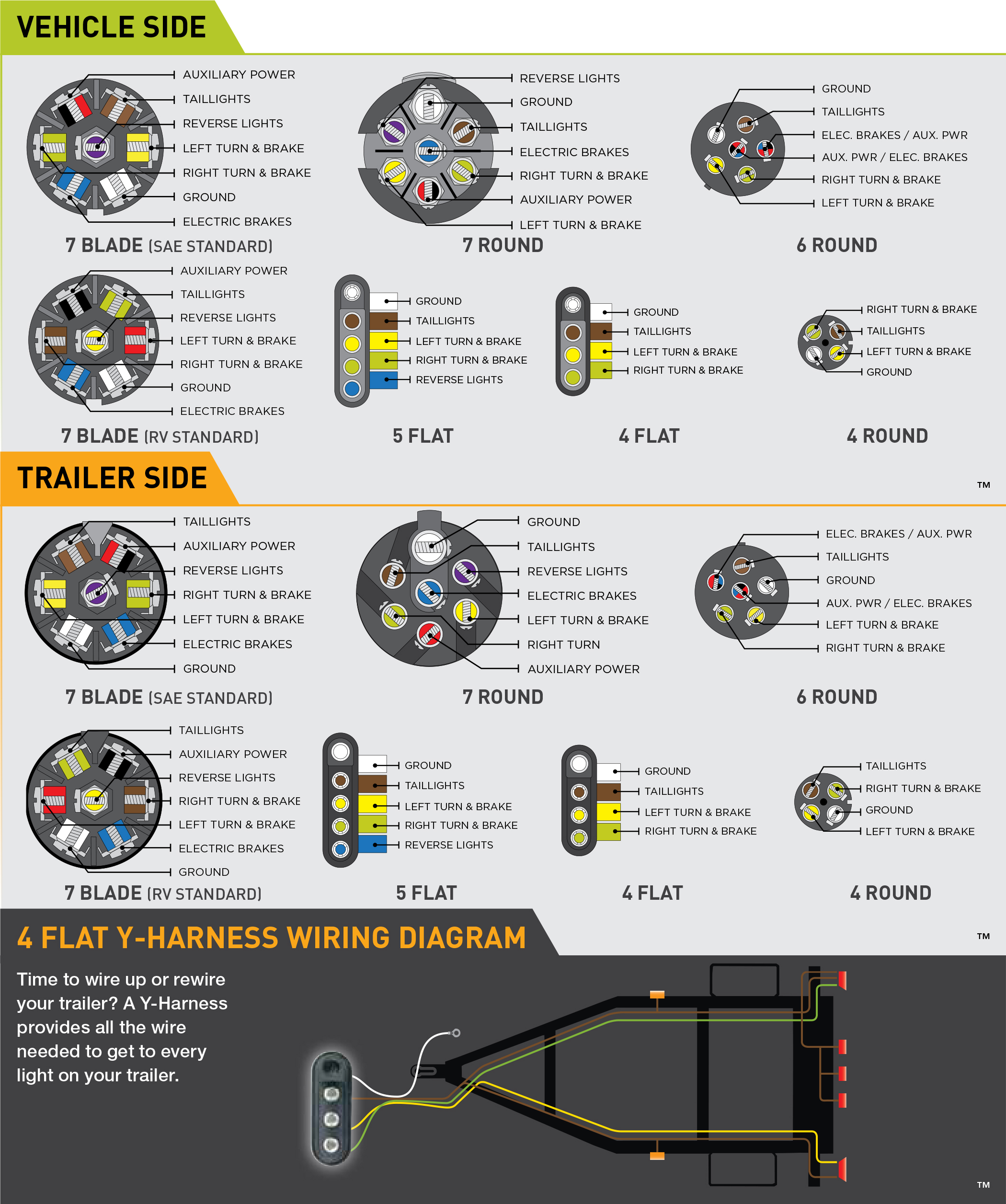
If you are looking at the inside of the trailer connector where the wires mount to the terminals starting at the top and rotating clockwise. This female trailer plug wiring diagram version is far more acceptable for sophisticated trailers and rvs.

Trailer Wiring Kit Diagram Wiring Diagram
Female trailer plug wiring diagram. This type of connector is normally found on utvs atvs and trailers that do not have their own braking system. We have an excellent wiring diagram on our website i will provide you a link so you can look at it. Above we have describes the main types of trailer wiring diagrams. Below is the generic schematic of how the wiring goes. The trailer wiring diagrams listed below should help identify any wiring issues you may have with your trailer. When wiring a trailer connector it is best to wire by function as wire colors can vary.
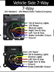
Note that this type of 4 pin connector is less common that 4 pin flat connector. Here is the diagram for 7 pin connector. 7 way plug wiring diagram standard wiring post purpose wire color tm park light green battery feed black rt right turnbrake light brown lt left turnbrake light red s trailer electric brakes blue gd ground white a accessory yellow this is the most common standard wiring scheme for rv plugs and the one used by major auto manufacturers today. 4 pin trailer wiring diagram. It may transfer electricity better compared to the connector is recommended for higher level electric in the car. 1 2 3 4 5 6 7 wiring diagram tailgate trailer sabs 1327 1981 1 left indicator yellow 1 2 auxiliary blue 3 earth white.
White pin to your floor. When shopping for trailer connectors remember that the male end is mounted on the vehicle side and the female on the trailer side.


