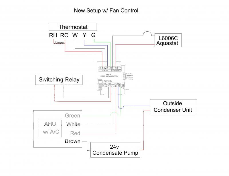
No rl2 rl3 rl4 rlcom switch ac in gnd vs d d gnd d d vs gnd d d vs thermister low medium high 2 way 3 way valve 1030v 100240v rs 485 thermister ac dc. Woods 1 scale none job sheet 1 of 13 7 ahu 2 wiring diagram 9 boiler panel 10 boiler panel expansion.

Unique Elcb Wiring Diagram Drawing Air Compressor Pressure
Fcu wiring diagram. Please subscribe to my channel. Here is a picture gallery about fan coil unit schematic diagram complete with the description of the image please find the image you need. Fan coil unit fcu fan motor control. 3 fcu wiring 5 ahu flow diagram 6 ahu 1 wiring diagram cover page pittsburgh air systems inc. 4 icp das co ltd. Fcu digital controller provided by mscc.
Wiring diagram for carrier fan coil readingrat pertaining to fan coil unit schematic diagram image size 639 x 600 px and to view image details please click the image. Wiring diagram fcu tpd series thermostat sc series 4 ch relay board rl1com rl1nc rl1. 1the mechanical systems control contractor mscc shall be responsible for the selection of providing installing all ddc controllers control devices to accomplish the sequence of. Example wiring diagrams typical 24vac control drawing refer to unit control enclosure for actual order specific drawings eti fcu fcrb installation operation and maintenance. Fan coil relay board fcrb installation operation and maintenance. Primary drain pan high level sensor hhws 0 fcu control diagram not to scale filter supply fan t occupancy sensor notes.
Hi in this video id like to show various samples of installing 13 amp fcu fused connection unit often used as a fused spur in a ring final circuits.


.jpg)
