Connect the black to the terminal labeled common and the blue wire to terminal in step 3 to open gate. When an exit wand is in use the automatic gate opener could be activated by a child on a.

Loop Sensor Wiring Diagram Door
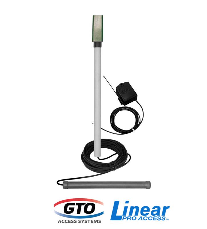
Exit wand wiring diagram. Wiring the exit wand note. Gto exit wand instructions 122811 3 4. Connect the yellow and braided ground wires to the negative side of power source. Connect the black to the terminal labeled common and the blue wire to terminal in step 3 to open gate. To wire or connect the exit wand to a mighty mule pro pro 1 locate the range adjustment board for the gate opening sensor or exit. Battery connect the red wire to the.
Connect the power input wires to power source. Insert the adapter board into the loop detector socket of the control board. Connect the power input wires to power source. This video is about wiring es deluxe exit want to apollo. This wiring is for connecting to richmond gate automation kits. Connect the black to the terminal labeled common and the blue wire to terminal in step 3 to open gate.
Connect the power input wires to power source. Connect the yellow and braided ground wires to the negative side of power source. Wiring the estate swing deluxe exit wand to liftmaster la400la412 duration. Gto exit wand instructions 091814 3 4. 29112018 29112018 7 comments on liftmaster la412u wiring diagram exit wand diagram. Keep the exit wand and the cable uncovered until all functions of the wand have been tested and the gate is successfully opening and closing automatically.
Battery connect the red wire to the positive side of power. Connect the yellow and braided ground wires to the negative side of power source. Battery connect the red wire to the positive side of power source. Gto exit wand instructions 122811 3 4.
Gallery of Exit Wand Wiring Diagram


