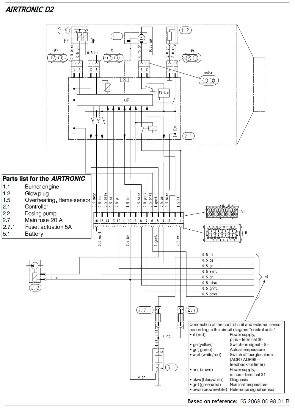
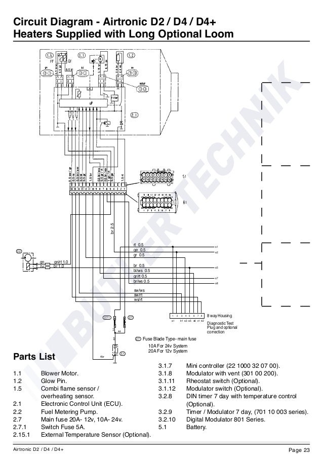
Circuit diagram airtronic d2 d4 short optional loom. 25 1906 05 12v 25 1907 05 24v page 19.

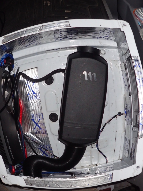
Fitting A Webasto Or Eberspacher Heater To A Boat Butlertechnik
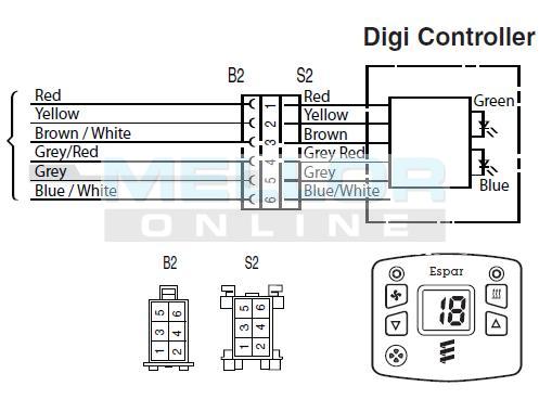
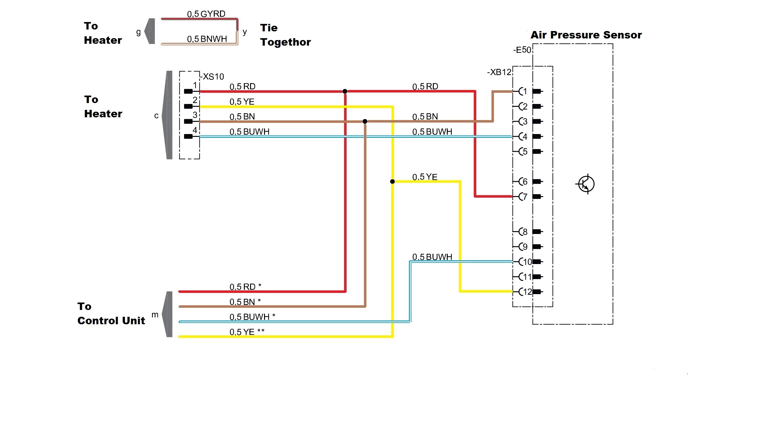
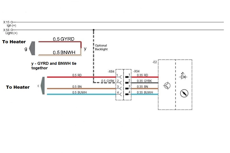
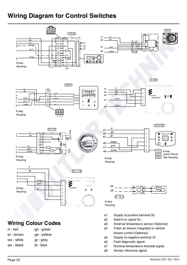
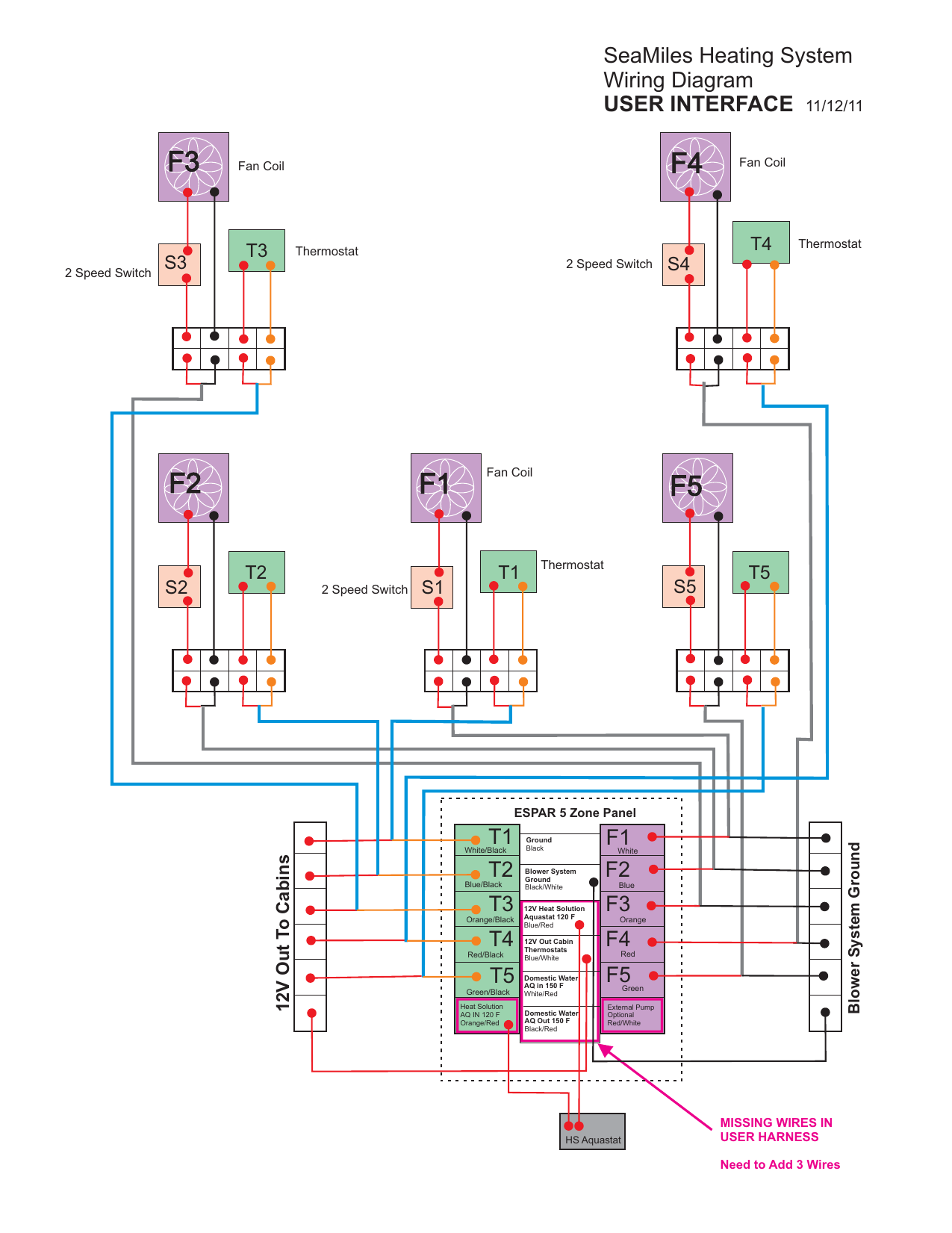
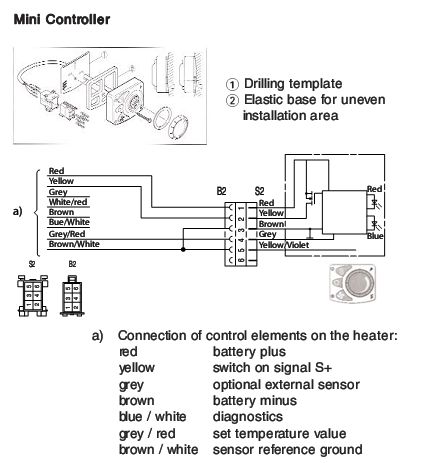
Espar wiring diagram. Rt 1 ge 2 br 5 blws 6 grrt 7 brws 8 8 way housing rt 1 ge 2 5 blws 6 grrt 7 brws. There is little clarity in espars instructions for those unfamiliar with reading technical wiring diagrams. Could you email the wiring diagram for the espar d2 heater. Espar airtronic airtronic m technical description installation operation and maintenance instructions. 25 2069 05 25 2070 05. Fuse in power harness.
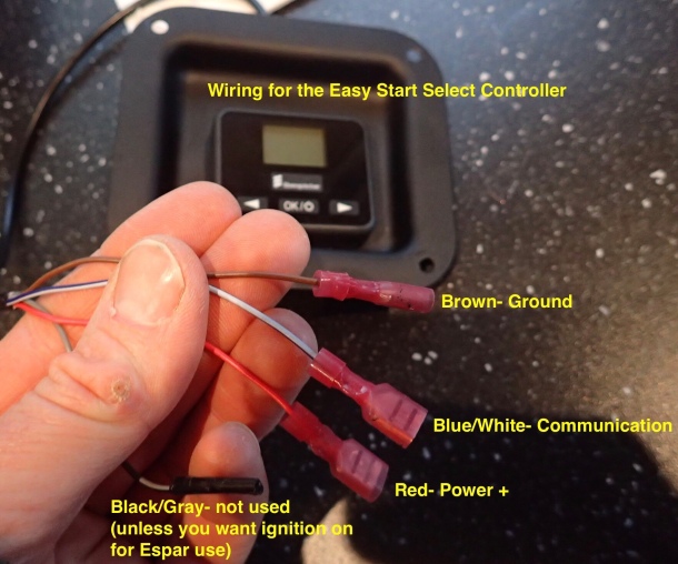
Wiring diagram for control switches. 51 heater wiring 28 52 parts list for the airtronic s2 and airtronic m2 circuit diagrams 28 53 circuit diagrams for airtronic 29 531 heater 29 532 cable harness 30 533 cable harness with adr 24 v only 31 54 circuit diagrams for control units 32 541 easystart pro 32. Wiring diagram for control switches. Wiring diagrams eberspacher airtronic d2 wiring diagram eberspächer airtronic d2 manual online. The other source of frustration is that the wiring harness supplied by espar is used for many of their products and various combinations of their products with a half dozen or so different controllers. Espar does not accept any liability for defects and damage which are due to installation or repair by unauthorised and untrained.
Page 18 wiring diagram d3lccompact glow plug negative pulsed models. Make sure vent hole is open. The wiring diagrams from espar are all over the place and without literally rewiring our heater i cannot say for 100 certain what is the correct way without using the external temp sensor. Third party controller espar onoff button switch or an espar timer to control the designated start time. Recommended service schedule airtronic d2 d4. Indicates that serious or fatal injury may result if specific guidelines are not followed.
Table of contents warning. January 23 2019 at 113 am. The key factor of the control is the fact it sends power to the heater on the yellow signal wire. In the case the heater does not operate no fan or circulating pump verifying there is output on the yellow wire is imperative. Airtronic airtronic d2 12 v airtronic d2 24 v airtronic d2 oem heaters12 v use instructions and parts based on wiring goes to the right side hous ing of the casing and 12 v tk airtronic d2 camper 12 v order no. Airtronic d2d4 installation troubleshooting parts manual espar airtronic for heater models release period airtronic d2 12 volt 25 05 airtronic.
Recommended periodic maintenance espar part number ca0 05 003. Page 1 airtronic d2d4 installation troubleshooting parts manual espar airtronic for heater models release period airtronic d2 12 volt 25 2069 05 00 00 november 2001 airtronic d2 24 volt 25 2070 05 00 00 november 2001 airtronic d4 12 volt. Heater wiring 27 parts list for heater circuit diagram 27 pin assignment for s1 connector 27 heater circuit diagram 28 pre start procedures 29.

