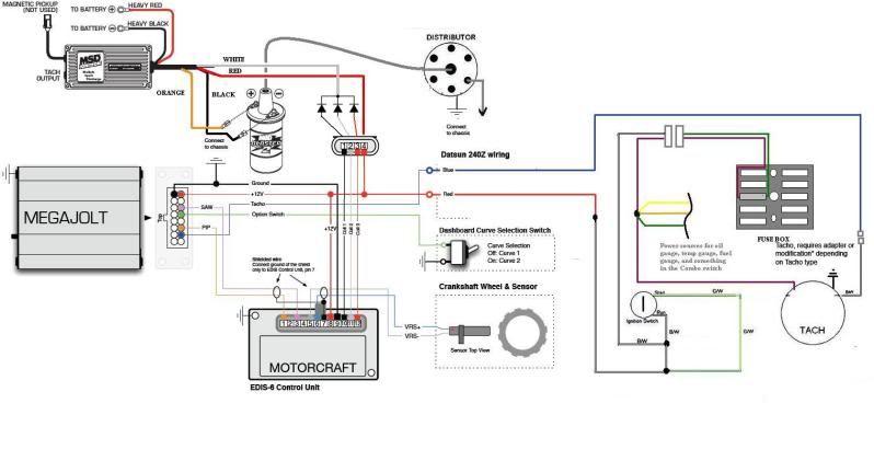
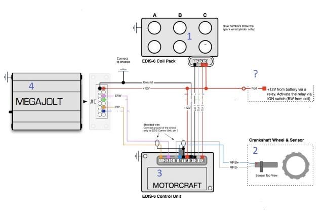
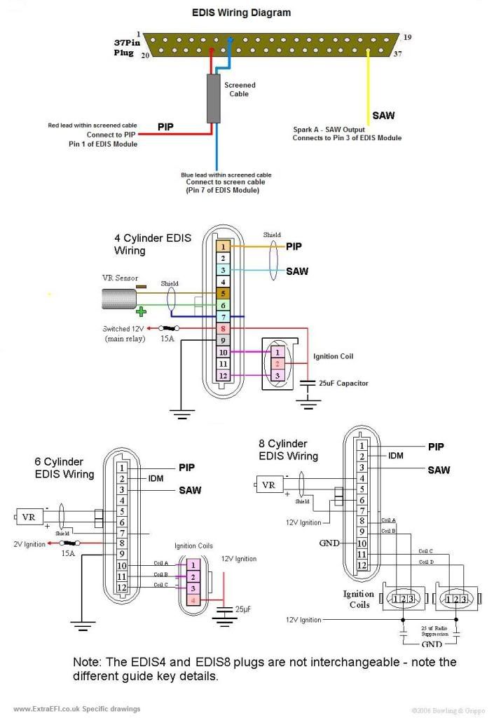
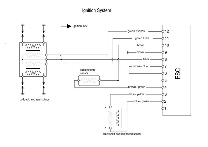
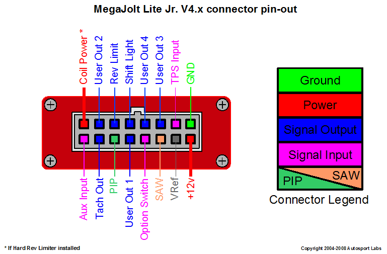
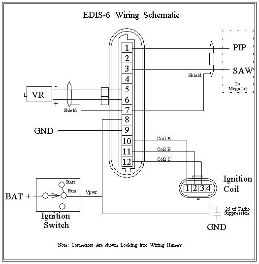
Im following the below and so far have the wires coming out of the edis unit with spade connectors on the end connecting then to the crank sensor etc. I popped open the lid on the edis 6 module and found that all ground pins 4 7 and 9 are connected together on the circuit board.
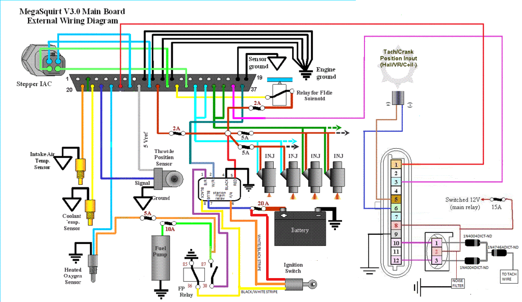
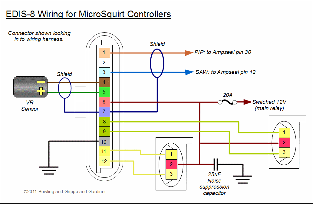
How To Use An Edis Module To Fire These Cop S Microsquirt
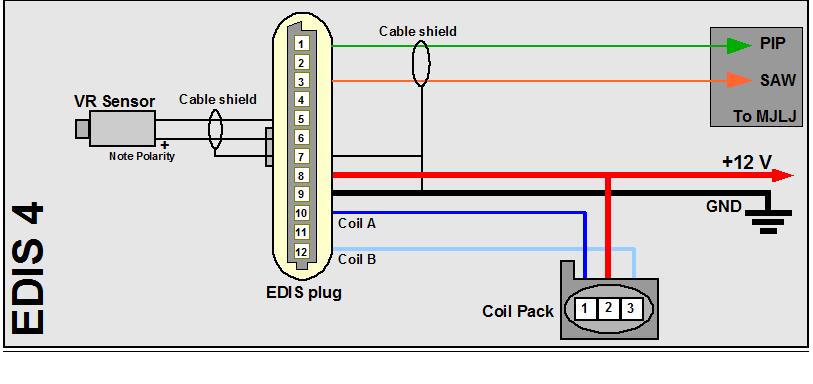
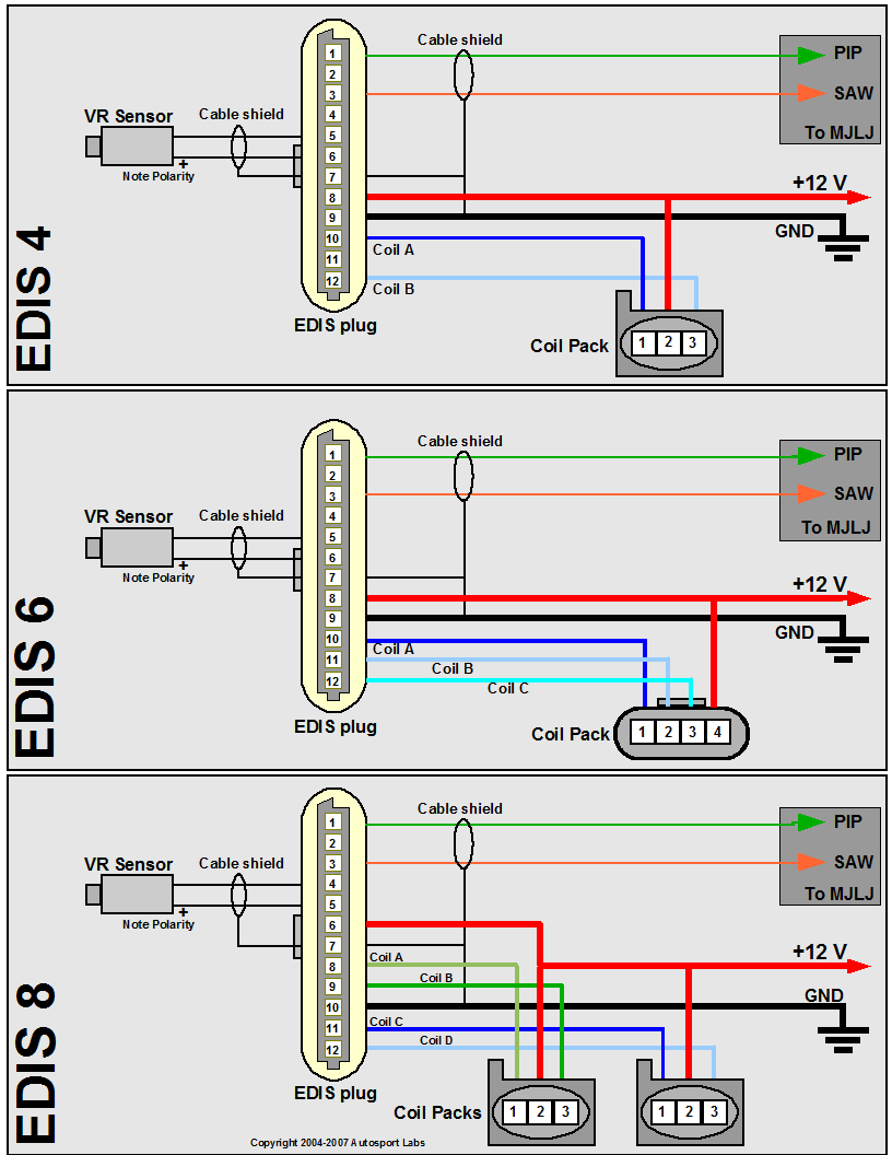
Edis 4 wiring diagram. Here is a picture gallery about edis 4 wiring diagram complete with the description of the image please find the image you need. Just wiring everything up to the edis 4 and megajolt and have a couple of questions. This page is intended for people who want to learn about the ford edis electronic distributorless ignition system. The ford edis system. Fords electronic distributorless ignition system edis is an ignition system that does not require a cam position signalit can function with just a variable reluctor crank position sensor and a 36 1 tooth wheel 36 1 means 36 teeth minus one and refers to 36 evenly spaced teeth one of which has been removed. It shows the components of the circuit as simplified shapes and the capacity and signal contacts in the midst of the devices.
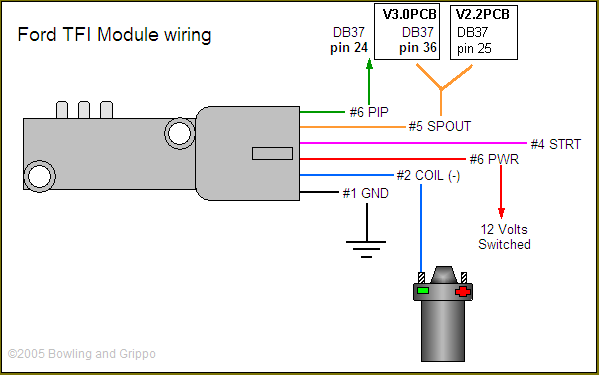
Pin 1 is usually marked on the connector. Note that the edis 4 and edis 8 key are similar but swapped from end to end. Firstly am i doing it right and secondly how the heck do you connect the cable shield. Ford edis 4 wiring diagrammsextra doc ms1extra ms extra ignition hardware manual htmthe v3 0 pcb has 4 spare connectors spr1 to 4 these can be used for various inputs and outputs for the following circuits as they are ford edis 4 wiring diagrammegamanual ms2 tfi htmtfi ignition control with megasquirt ii thick film ignition tfi modules were used on ford vehicles with distributors from the early 1980s to the mid 1990s. Edis 4 wiring diagram is among the. Of the two coil drivers one was wired with two coil primaries in parallel and the other.
Here are the edis external wiring diagrams for the edis4 edis 6 and edis 8. The oscilloscope plot illustrates the current consumption of a typical edis 4 ignition system. In this test a 100mv100a shunt was used to measure current consumption for both coil drivers. We hope this article can help in finding the information you need. Do not attempt to connect them you will ruin the module wiring andor coil packs. Alternate coil wiring multiple coil primaries per driver.
Edis 4 wiring diagram wiring diagram is a simplified up to standard pictorial representation of an electrical circuit. The pinouts and diagrams are taken from how to understand service and modify ford electronic fuel injection electronic engine control by charles probst the technical information on the saw and inner workings of the edis module are taken from ford patent 4922874. Heres the edis 6 wiring diagram that i edited with the corrections. With this setup the edis module will fire the ignition at 10 degrees advance as a default unless the module receives a saw command discussed below. Edis ignition control with megasquirt ii. In all case the clip is the most useful guide to the pin numbering.
The edis 4 and edis 6 modules have different advance settings need to determine these values from measurement. Edis 4 wiring electrics rhocar community in edis 4 wiring diagram image size 801 x 347 px and to view image details please click the image.
