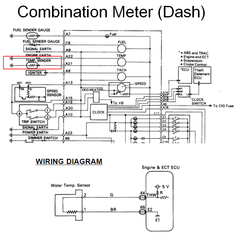
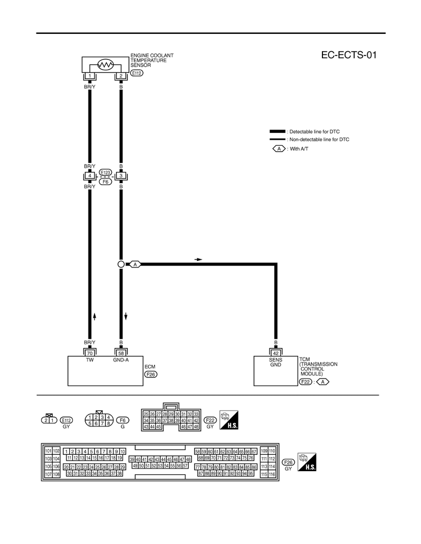
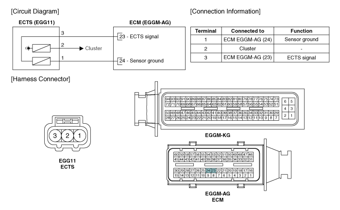
Wiring related to each system is indicated in each system circuit by arrows from to. A bad engine coolant temperature sensor affects engine performance.

Suzuki Gsx R 1000 Service Manual Dtc C15 P0115 H L Ect
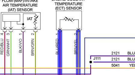
Ect sensor wiring diagram. That one is in the left cylinder head. It shows the components of the circuit as simplified shapes and the capability and signal contacts surrounded by the devices. This video explain its electrical connections to the ecm or from an electrical perspective. It was a wire soldered on to the back of the sensor ok4450 said youre not confusing an ect sensor with a temp sensor used for other fuctions are you. When overall connections are required see the overall electrical. Ect with 38 inch 18 npt thread the most common ect sensor among gen i engines installs into a 38 inch 18 npt threaded hole in the engines intake manifold.
Learn how the ect connects and reports its value. Coolant temp sensors wires are shorted to each other. Internal wiring for each junction block is also provided for better understanding of connection within a junction block. Coolant temp sensor is bad. The ect is a main input to the ecm or engine computer. This code indicates that the pcm is seeing a high voltage drop across the ect sensor which its translating as an extremely hot coolant.
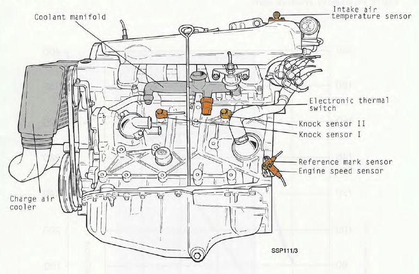
The engine coolant temperature ect sensor responds to change in engine coolant temperatureby measuring engine coolant temperature the ecm engine control module knows the average temperature of the engine and tells the computer what the engine temperature is so that optimum driveability is realized while the engine is warming up and when the engine has reached operating temperature. The engine coolant temperature ect sensor test is simple and can help you fix your car faster. Ls series vehicles fitted with this two wire sensor use the pcms data stream output to display the calculated engine coolant temperature. As in temp gauge operation cooling fan sensors etc etc nevada545 said the coolant temp sender for the gauge has one wire dark green. Wiring diagram at the end of this manual. Engine coolant temperature sensor wiring diagram wiring diagram is a simplified normal pictorial representation of an electrical circuit.
Coolant temp sensors wires are shorted to ground. Engine coolant temperature ect circuit high input. It may cause a constant lean airfuel mixture causing the engine to stall or idle rough. You can do it at home using a digital multimeter and a cooking thermometer.

