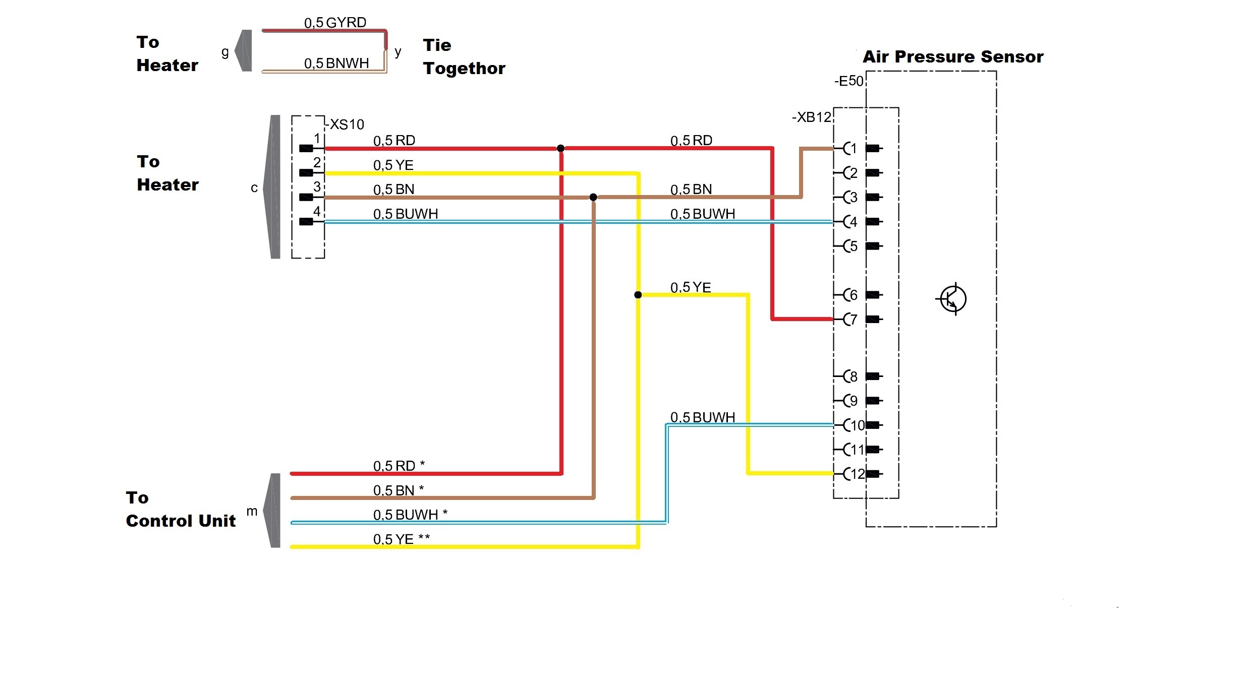
However eberspächer uk ltd. Eberspacher d4 wiring diagram wiring diagram is a simplified all right pictorial representation of an electrical circuit.

Ry 8737 Espar D2 Heater Wiring Diagram Download Diagram
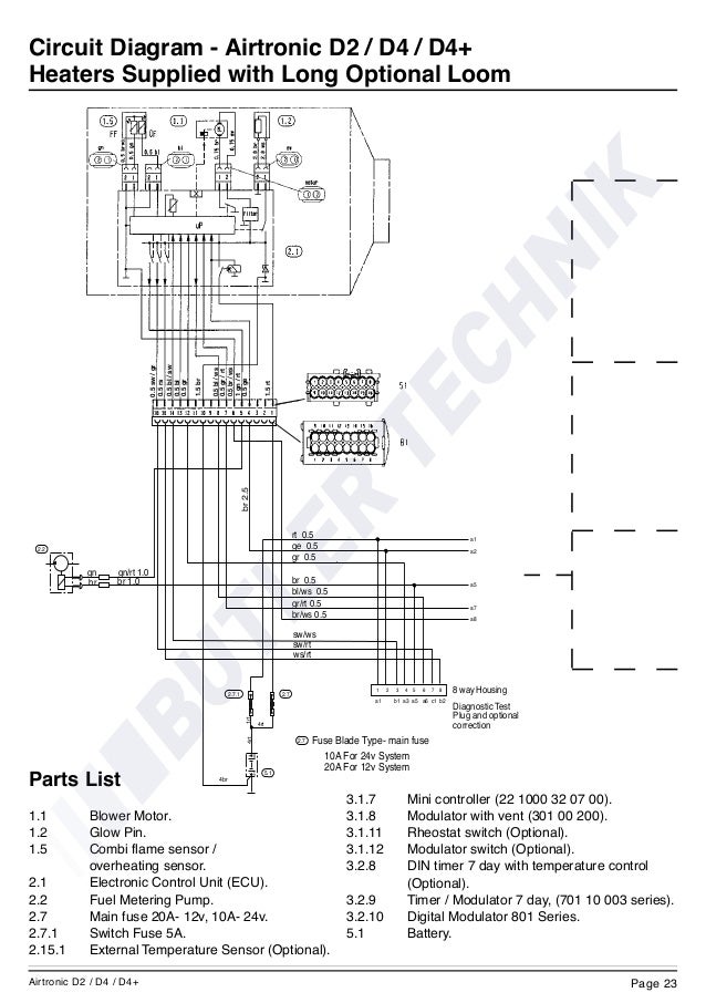
Eberspacher d4 wiring diagram. The installation manuals cover many of the details and i recommend downloading and studying the manual before starting see manuals page. A world of comfort. Airtronic d3 12 v 25 2317 05 00 00 airtronic b4 12 v 20 1812 05 00 00 airtronic d4 12 v 25 2113 05 00 00 airtronic d4 24 v 25 2114 05 00 00. Have a policy of continuous improvement and reserve the right to amend any specifications without prior circuit diagram airtronic d2 d4 short optional loom. Wiring diagram for control switches. Based in ringwood hampshire eberspächer uk limited is a wholly owned subsidiary of eberspächer climate control systems gmbh of germany.
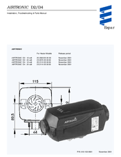
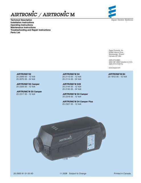
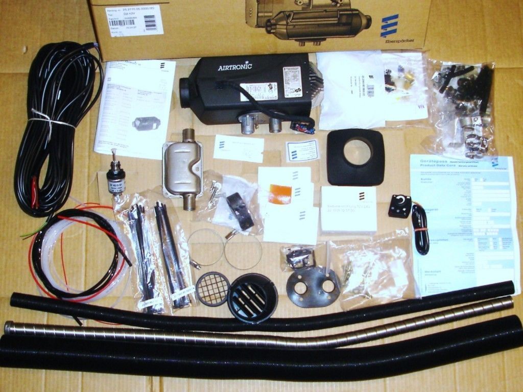
The airtronic d2 d4 d4s 24 volt is suitable and certified for installation in. Wiring connections cause many people problems when changing or maintaining their systems. Airtronic d2d4 installation t roubleshooting parts manual espar pn. The airtronic d4 is a more powerful version of the airtronic d2 for larger scale heating environments whilst only being slightly larger it offers optimised fuel efficiency a range of operation modes and unsurpassed safety standards. 610 103 0901 november 2001 airtronic for heater models release period airtronic d2 12 volt 25 2069 05 00 00 november 2001 airtronic d2 24 volt 25 2070 05 00 00 november 2001 airtronic d4 12 volt 25 2113 05 00 00 november 2001 airtronic d4 24 volt 25 2114 05 00 00 november 2001. Eberspächer airtronic d4 manuals manuals and user guides for eberspächer airtronic d4.
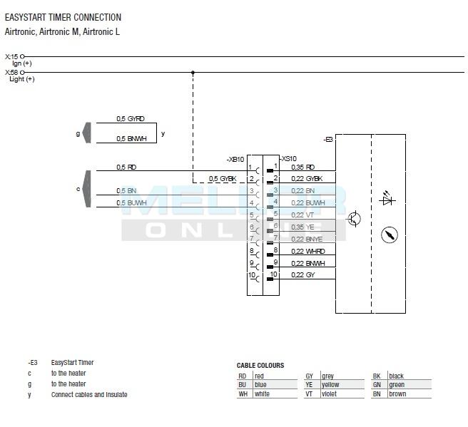
Eberspacher wiring modern air heaters airtronic d2 d4 d5 d1lcc d3lcc d1lc d3lc d5lc. We have 4 eberspächer airtronic d4 manuals available for free pdf download. Wiring diagram for control switches. Airtronic m order no. It shows the components of the circuit as simplified shapes and the facility and signal contacts between the devices. Particular to the electric wiring circuit diagrams the fuel supply the combustion air and exhaust gas duct.
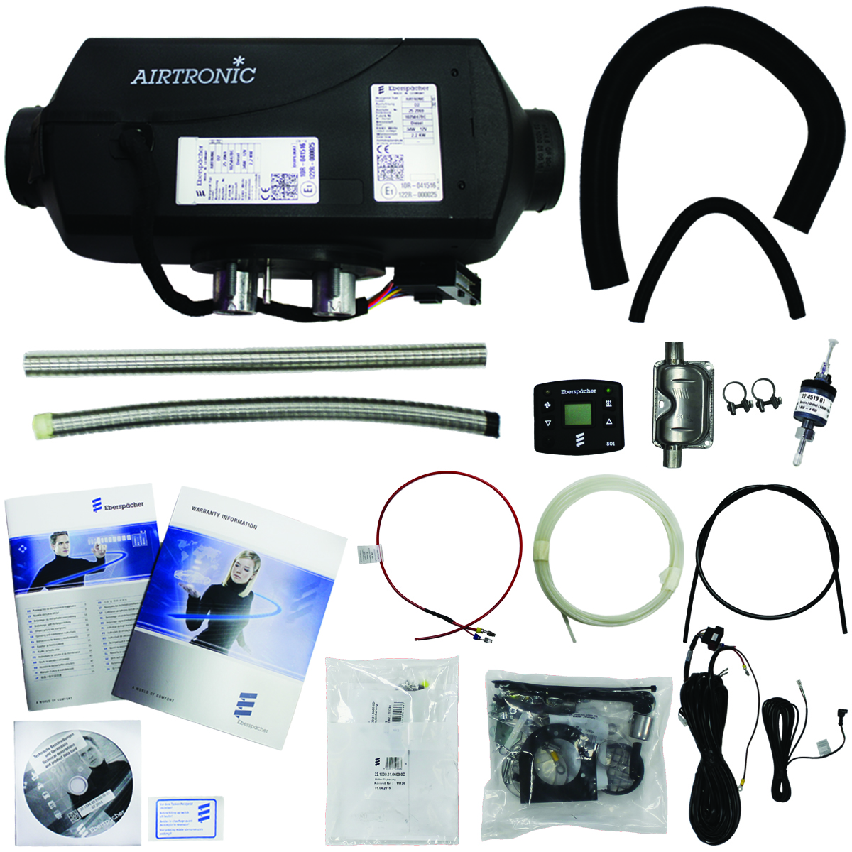
Technical description installation operation and maintenance instructions operating instructions and service book installation manual operating instructions. Only the control elements provided and or. We were established in 1977 originally to introduce diesel fuelled independent heating systems into the uk and eire for car commercial vehicle and marine markets and to create a nationwide network of dealers to provide a quick and efficient service to. Circuit diagram airtronic d2 d4 short optional loom circuit diagram airtronic d2 d4 heaters supplied with short optional loom rt 05 ge 05 gr 05 swrt 05 gnrt 10 br 10 br 05 blws 05 grrt 05 brws 05 8 way housing gr 05 br 05 319.

