Pc rs232 port to plc rs232 port using the wiring dvpacab2a30. Pc usb port to plc rs485 port using the device ifd6500 delta usb rs485 converter.
How To Do Connection Of Delta Plc Dvp 14ss2 Wiring By
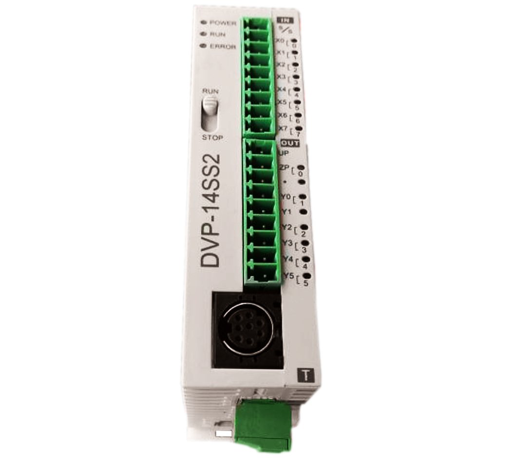
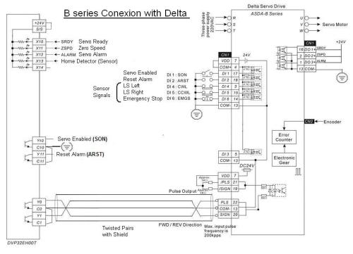
Dvp14ss2 wiring diagram. A2 installing the usb in windows 8. Example on sending sdo through the ladder diagram. We provide all delta ac drives vfds delta ac servo motors delta rotary optical encoders delta motion control network delta programmable logic controller delta human machine interfaces delta text panels delta temperature controllers delta industrial fieldbus solutions delta pressure sensor delta brushless dc motors as well as delta brushless dc drives. The dvp 14ss211r features high speed counters a flexible serial port real time monitoring and an expansion bus that allows matching modules to be mounted on the right side of the plc without external wiring. Canopen network node state display. Pc ethernet port to plc dvpen01 sl module need compatibility with high speed bus communication pc to plc trough delta hmi direct link.
4 input 0 to 10v 10 to 10v 4 to 20ma 0 to 20ma resolution. The analog output module. Automation hub 9966 views. 1 the junction box at the pv array wiring from pv array to the disconnect switch on the house the disconnect switch the wiring from the disconnect switch to the circuit breaker panel. In this video the connection to the wiring of delta plc dvp 14ss2 has been done with an easy way. The enphase wiring diagram is here.
How to do mitsubishi plc wiring connect npn sensor with plc pnp sensor conect with plc lecture 1 duration. 0 10v dimming wiring diagram 0 10v dimmer switch leviton ip710 lfz or equal for other types of dimming control systems consult controls manufacturer for wiring instructions switched hot black switched hot red typical low voltage dimming wires purple gray typical electrical panel hot black typical 120v or 277v 60 hz neutral white. A1 installing the usb driver in windows 7. The dvp ss2 series is delta electronics second generation of slimline industrial plcs. Here is a very simple diagram of the micro inverter system. Wire burnout detection 1 to 5v 4 to 20ma offset gain setting left side extension.
This video describes how to wire your controller. I did the wiring in this order. Ferdowsi university of mashhad. Converting analog signals to binary data in high speed.


