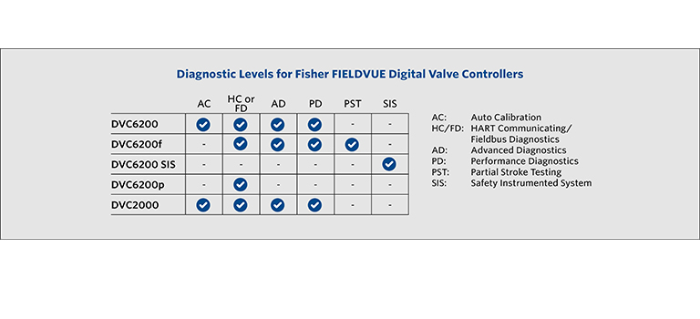
Fieldvue dvc6200 digital valve. Refer to the fisher dvc6200 sis quick start guide d103556x012 for mounting and configuration.
Masonry 3 Columns Vrc
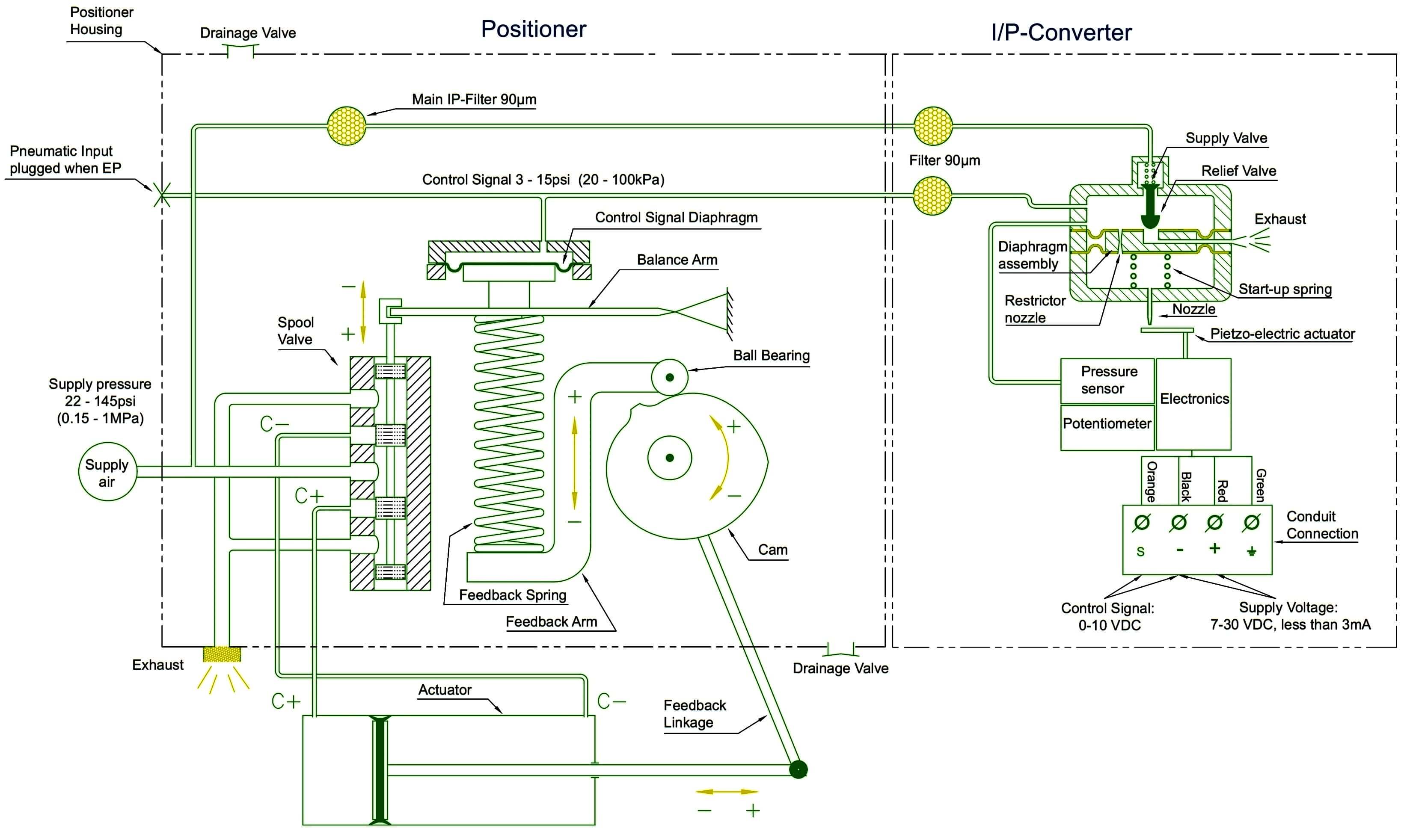
Dvc6200 wiring diagram. Dvc6200 housing is within the valid range on the magnet assembly throughout the range of travel. You can obtain general information concerning software revision level messages tag descriptor and date. In addition to the traditional function of converting an input current signal to a pneumatic output pressure the dvc6200 digital valve controller using the hart communications protocol gives. Fisher 657 vertically align the magnet assembly so that the center line of the. If a lcp200 is used refer to the fisher lcp200 instruction manual d104296x012 for wiring configurations and mounting. Dvc6200 hw1 digital valve controller january 2018 2 specifications this product was intended for a specific range of service conditionspressure pressure drop process and ambient temperature temperature variations process fluid and possibly other specifications.
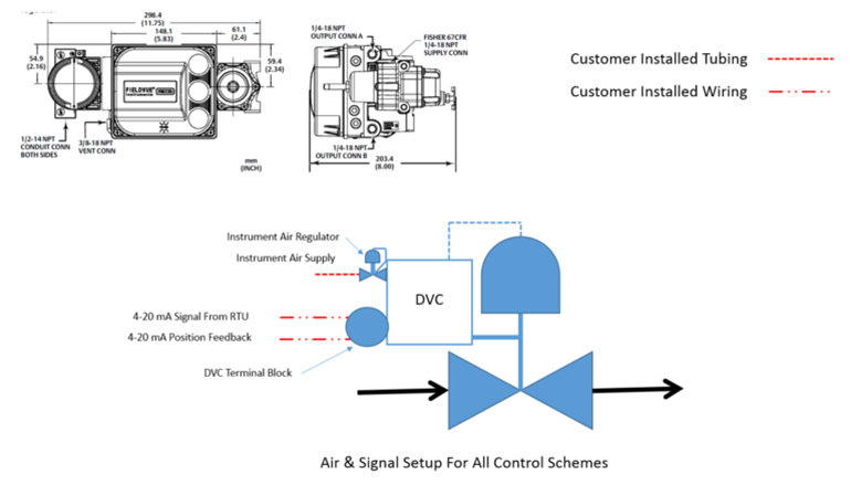
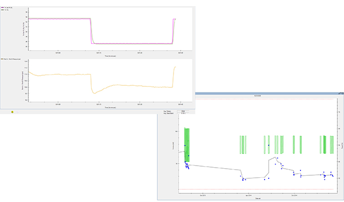
These are basic schematics that have been developed to provide details of the connections between the control system and user interface. Dvc6200 sis flat head screwdriver 3 mm thin blade wiring terminations phillips screwdriver. Page 112 dvc6200 digital valve controller fm 93 principle of operation iecex 94 dvc6200 88 hart communication 88 natural gas as supply medium 15 70 printed wiring board assembly number of power ups device record 64 maintenance 74 removing 74 replacing 75 processor impaired alerts 42 protection 26 34 output pressure sensor. Diagnostic tests can be run locally with ease and mobility using the 475 field communicator with valvelink mobile software. Parts and procedures are common across the dvc6200 series. Instruction manual wiring practices d103605x012 february 2017 section 2 wiring practices22 control system requirements there are several parameters that should be checked to ensure the control system is compatible with the dvc6200 digital valve controller.
Page 126 instruction manual principle of operation may 2013 d103409x012. Field ruggedized and portable tools enable easy valve setup and. Dvc6200 digital valve controllers figures 11 and 12 are communicating microprocessorbased currenttopneumatic instruments. The dvc6200 sis can operate through a command signal from either a dcs basic process control system bpcs or logic solver safety instrumented system sis. Quick start guide d103556x012 dvc6200 digital valve controllers june 2019 7 for airtoclose actuators eg. You can perform several operations with the dvc6200 digital valve controller.
Fieldvue dvc6200 digital valve controller mounted on a fisher sliding stem valve actuator w9643 figure 12. Catwalks ladders or other difficult locations no longer present a barrier. Drawings indicated as pst only. Fieldvue dvc6200 digital valve controller block diagram input signal 4 20 ma hart valve travel feedback printed wiring board drive signal terminal box output a auxiliary terminals pneumatic converter relay supply pressure. Do not expose the product to.


