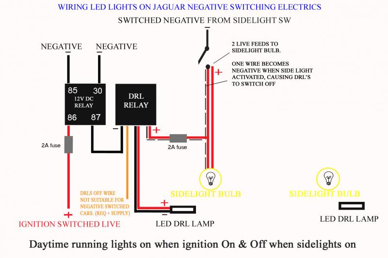
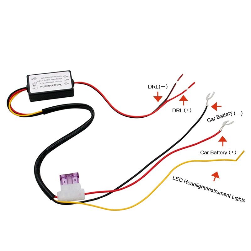
In addition any local auto electrician should be able to set this up for you if needed. 4 remove the no.

De 3604 Headlamp Delay Modulecar Wiring Diagram Download Diagram
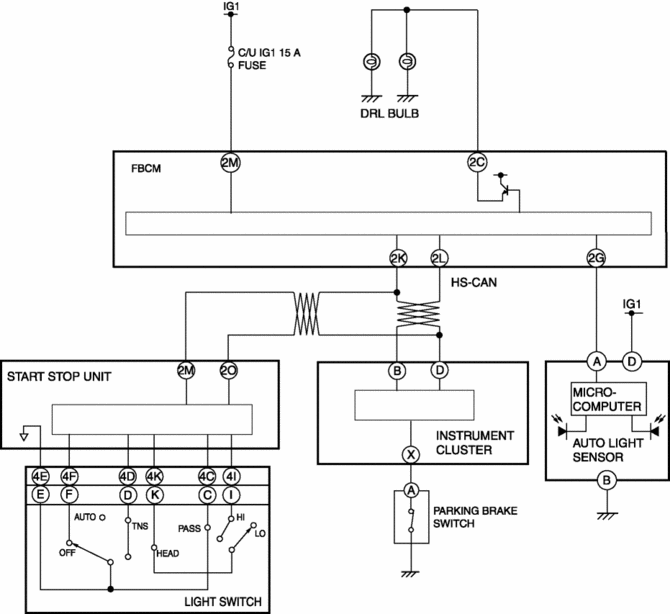
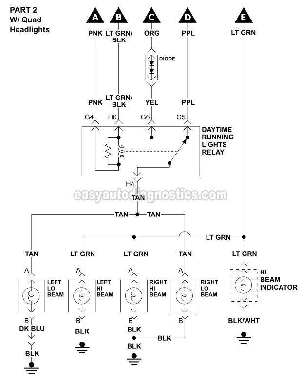
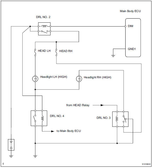
Drl wiring diagram. Suitable automotive electrical wiring. The drl system is different. You cannot use this module with incandescent bulb type lighting this will damage the module instantly if you attempt to connect the drl module to incandescent lighting. Inspect daytime running light relay marking. Whats a drl or day time running light device. The main body ecu controls the daytime running light no.
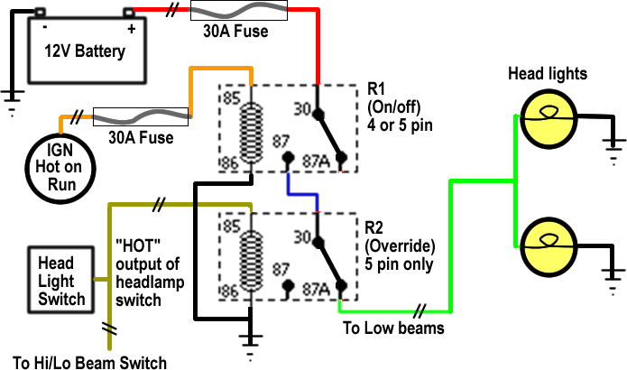
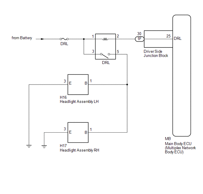
3 relay and no. 4 relay from the engine room no. If it sees daylight and the parking brake isnt set the bcm provides ground to the control coil in the drl relay. Measure the resistance of the relays. The way to do this is by wiring the harness that is included with your headlightsdepending on the headlights feature you get there will be two types of drl harness. For headlights with activation light and sequential signal.
Once the control coil has ground the contacts close and the relay provides power to the drl lights. The bcm looks at the input from the ambient light sensor. One of the key features of our headlights is to have the ability to run the drl strips in the day without having to activate any of your lighting controls manually. The purpose of this module is to activate daytime running lights on any lighting on a car that is led lighting. A drl is a safety car lighting device specifically assigned to moving vehicles for increasing the conspicuity of the vehicle during day time especially when the daylight is accompanied with fog or during dull overcast daysit is normally fixed just beside the headlamps on either sides. Normally a drl system is in the form of.
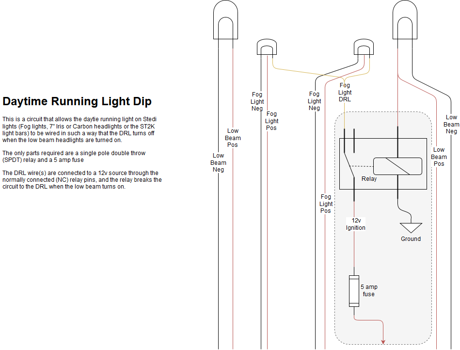
A number of our products include daytime running lights and below is a diagram for customers interested in wiring them up via a relay to allow them to turn off when the low beam headlights are turned on.

