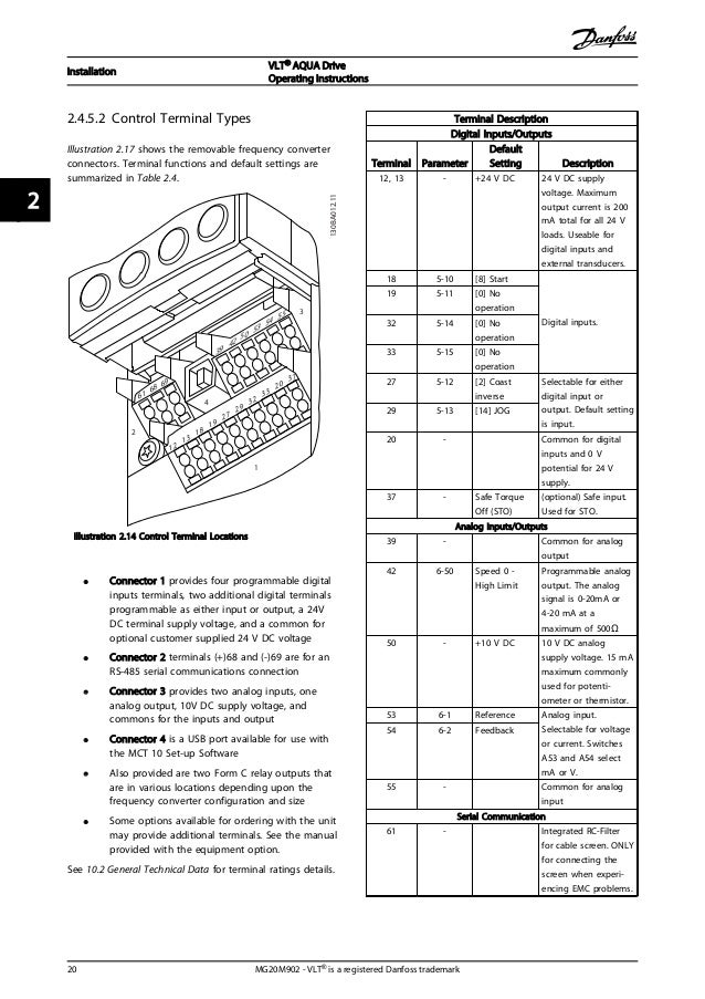
53 wiring diagram 21 54 fuses 22 55 electrical kit installation 24 56 dc bus fuse installation 24. See table 12 for their functions.

Danfoss Vlt 5000 Instruction Manual Manualzz
Danfoss vlt wiring diagram. Contents 1 introduction 4 11 purpose of the manual 4. Diagrams below figure a and b. Mg35b102 vlt is a registered danfoss trademark principle of the vlt 3500 hvac a frequency converter rectifies ac voltage from the mains supply into dc and then modifies this into a variable ac voltage with variable amplitude and frequency. This design guide can be used for all vlt series frequency converters with contact danfoss drives for further infor 6 wires out of motor delta con. Vlt 5000 5000 flux 6000 hvac 8000 aqua profibus 4 mg90g102 vlt is a registered danfoss trademark. 7111 fixed variable speed pump wiring diagram 127 7112 lead pump alternation wiring diagram 127 7113 cascade controller wiring diagram 128 7114 startstop conditions 129 8 installation and set up 130 81 installation and set up 130.
This design guide for danfoss vlt. Uration with a slave not manufactured by danfoss you should refer to the information in the respective manuals. 175ha49011 touching the electrical parts may be fatal even after the equipment has been disconnected from mains. 510 control wiring connections 31 5101 control cable routing 32 5102 control wiring 33. Danfoss vlt 2800 wiring diagram line and components ac line transformer wires fuses and the danfoss vlt controls both the amplitude and the. 44 wiring schematic 12 45 access 14 46 motor connection 14 47 ac mains connection 15 48 control wiring 16 481 control terminal types 16.
15 block diagram of the frequency converter 4 16 enclosure types and power ratings 4. 48 control wiring 17 481 control terminal types 17. Using vlt6002 6005 200 240 v. Danfoss vlt. Mains supply 3 200 220 230 v ac 50 60 hz 3 380 400 415 v ac 50 60 hz. 435 cascade controller wiring diagram 105 436 fixed variable speed pump wiring diagram 106 437 lead pump alternation wiring diagram 106 5 special conditions 110 51 manual derating 110 52 derating for long motor cables or cables with larger cross section 111.
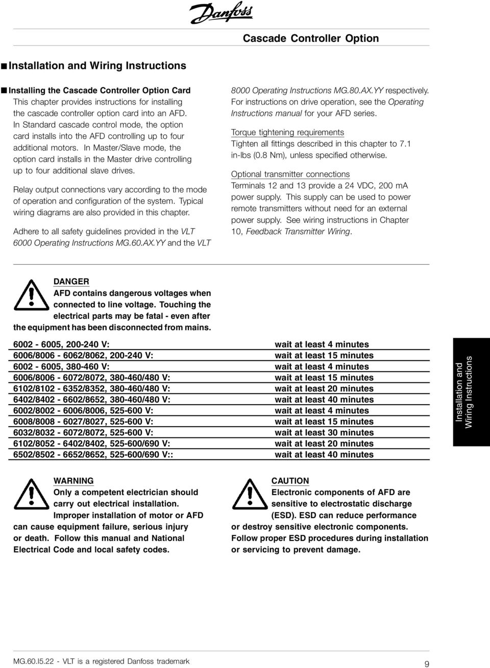
Vlt 6000 hvac introduction to hvac warning. 35 wiring schematic 16 36 controls 18 361 control principle 18 362 fc 301 vs. Fc 302 control principle 19 363 control structure in vvc 20 364 control structure in flux sensorless fc 302 only 21 365 control structure in flux with motor feedback fc 302 only 22 contents vlt automationdrive fc 301fc 302 design guide 025 75 kw. 143 block diagram of the frequency converter illustration 13 is a block diagram of the internal components of the frequency converter. Wait at least 4 minutes.


