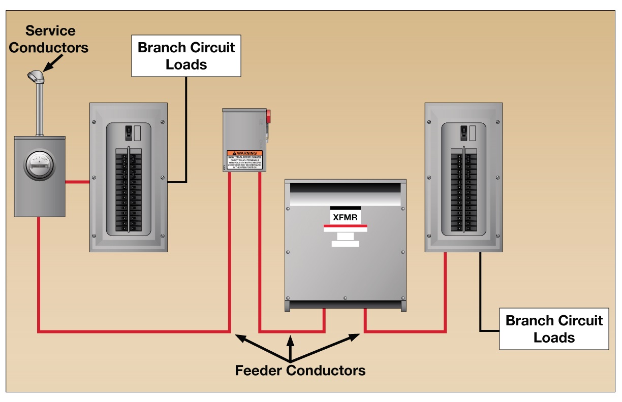
It is up to the electrician to examine the total electrical requirements of the home especially where specific devices are to be located in each area and. When and how to use a wiring diagram.

Rc 3711 Three Phase Electrical Wiring Installation At Home
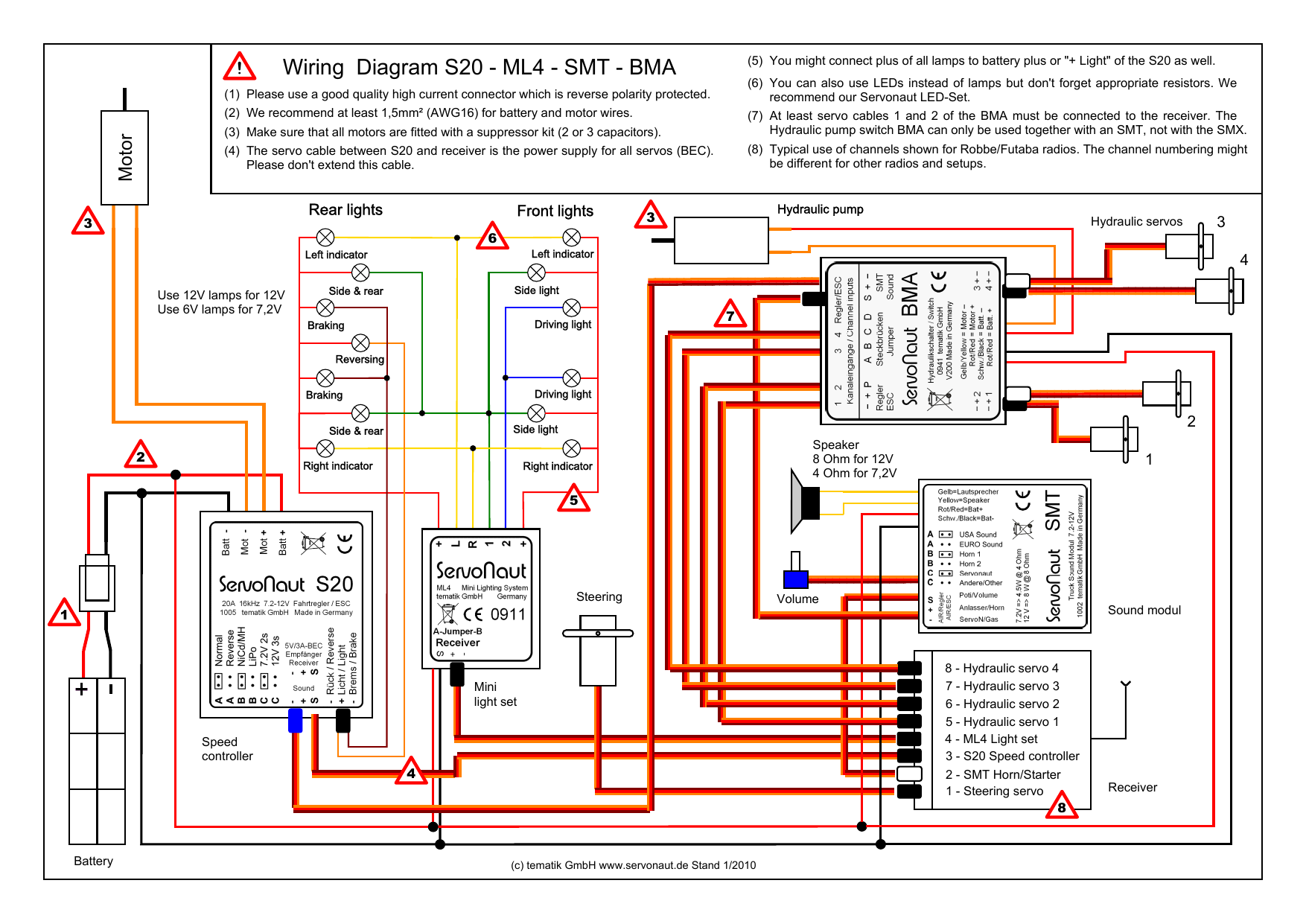
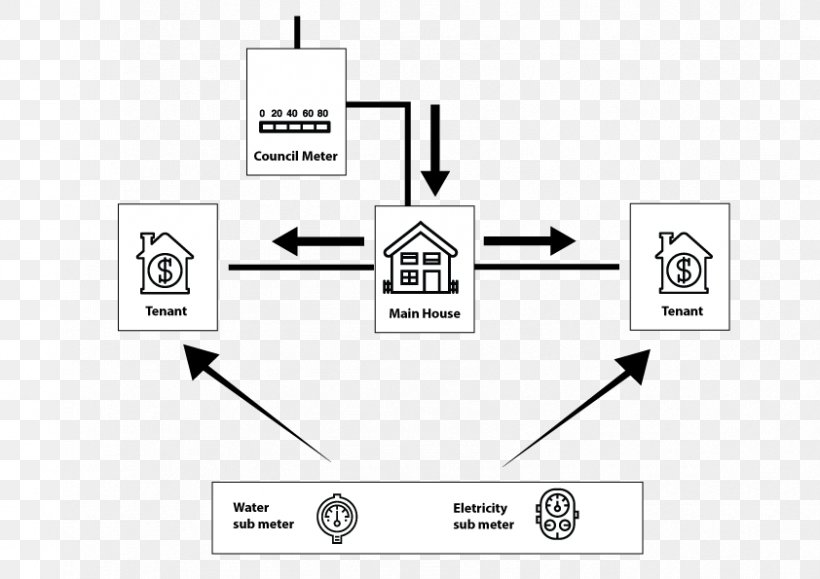
Council wiring diagram. A small wiring diagram of the light barrier located in the housing out of it conductors for power and lighting. Wire is often run in concealed areas and at the ends where it is visible its usually bundled with a bunch of other wires. Mount photocell carried by the support arm and selected the place where the device is exposed to direct sun rays. With the light at the beginning middle and end a 3 way dimmer multiple lights controlling a receptacle and troubleshooting tips. What is a wiring diagram. It shows how the electrical wires are interconnected and can also show where fixtures and components may be connected to the system.
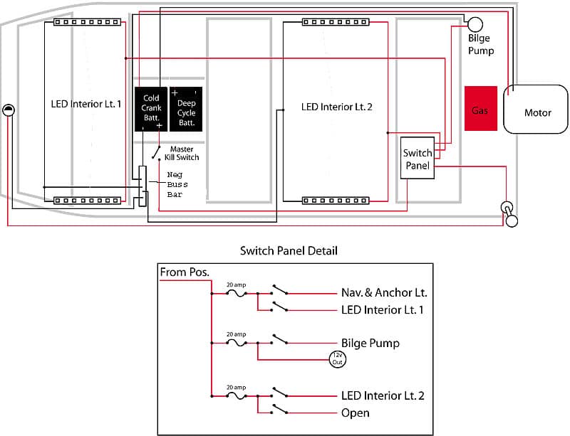
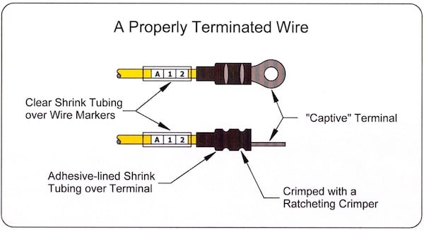
Wiring diagrams for 3 way switches diagrams for 3 way switch circuits including. The next key advantage of ladder wiring diagrams over drawing circuits is the way they are physically laid out so that they are indexable meaning device names can give you the page and rung number that the device can be found on in the ladder wiring diagrams. Tracing wiring runs in boats can be a painful task. A wiring diagram is a simple visual representation of the physical connections and physical layout of an electrical system or circuit. The good news is that most boatbuilders use the american boat and yacht council color codes for boat wiring. Wiring diagrams device locations and circuit planning a typical set of house plans shows the electrical symbols that have been located on the floor plan but do not provide any wiring details.
Also devices that may span multiple locations in a drawing such as a relay coil and. Adjusting the threshold is carried out using a special controller that enables to trigger in various conditions.


