Care must be taken to ensure that wiring or. The digital compressor controller is designed only for single phase copeland scroll.

Read Or Download Fan Light Combo Wiring Diagram For Free At
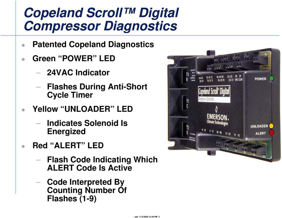
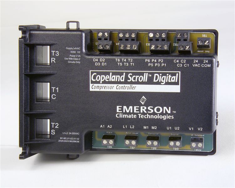
Copeland digital compressor controller wiring diagram. The digital compressor controller provides control protection and diagnostics for the digital compressor system. Getting from point a to aim b. Copeland compressor wiring diagram copeland scroll commercial compressors 10hp find complete details about copeland compressor wiring diagramthe digital compressor controller is the electronics interface between the copeland scroll digital compressor or the copeland discus digital compressor and the system controller. Separate copeland digital compressor controller in system wiring. The digital compressor controller is the electronics interface between the copeland scroll digital compressor or the copeland discus digital compressor and the system controller. Literally a circuit is the path that allows electricity to flow.
Discus digital is not compatible with intelligent store discus 10. Capacity to the digital compressor controller via an analog signal. A wiring diagram is a streamlined traditional photographic depiction of an electric circuit. A very first look at a circuit layout may be complex yet if you could review a train map you could review schematics. Copeland scroll compressors have a voltage tolerance of 10. See tables 1 2 3 and 4 for part number details.
The compressor terminal box has a wiring diagram on the inside of its cover. It reveals the components of the circuit as simplified forms and the power as well as signal connections between the tools. Master controller the copeland discus digital compressor is approved for use with e2 v23 facility management system and higher. For digital low temperature compressors using liquid injection zfdk5 or k4 use a current sense relay for the liquid line solenoid. Here is a picture gallery about copeland compressor wiring diagram complete with the description of the image please find the image you need. Copeland condensing unit wiring diagram copeland service manual pertaining to copeland compressor wiring diagram image size 830 x 478 px and to view image details please click the image.
The copeland scroll compressors inherent. Single phase compressors are connected to the common c start s and run r connections. Refer to original equipment wiring diagrams. Copeland compressor wiring diagram a newbie s guide to circuit diagrams. Digital solenoid this is a 110vac220vac solenoid output labeled sol which is used to control the digital operation. The type of compressor and the application determine the version of digital compressor controller that can be used.
Digital capacity control vs. The objective is the very same. Compressor wiring diagrams with motor winding connec data copeland scroll compressors and electrical. Before connecting the compressor ensure the supply voltage the phases and the frequency match the nameplate data. Three phase compressors are connected to. Ac copeland scroll.
Variety of wiring diagram for copeland compressor. The compressor should be specifically identified.


