Cat5 to xlr wiring diagram. Variety of cat 5 wiring diagram pdf.

Yb 7322 Images Of Cat5 Poe Wiring Diagram Wire Diagram
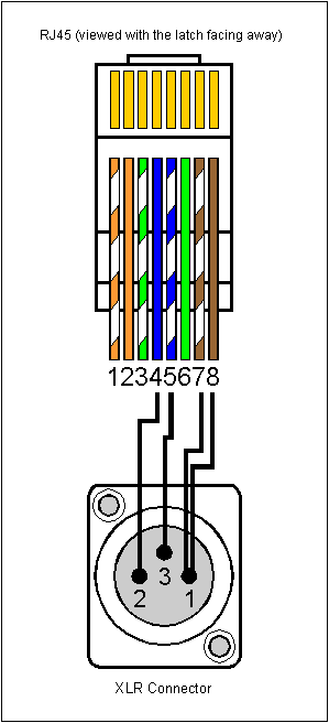
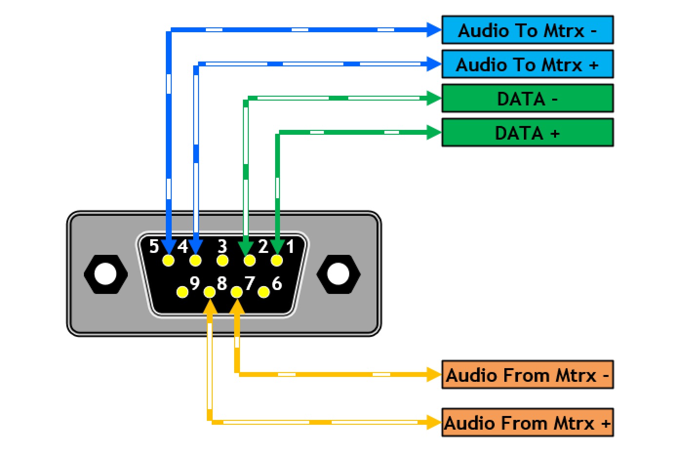
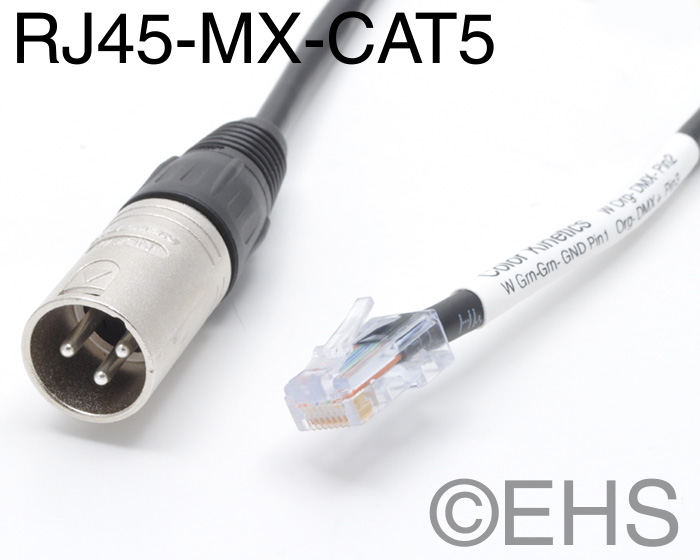
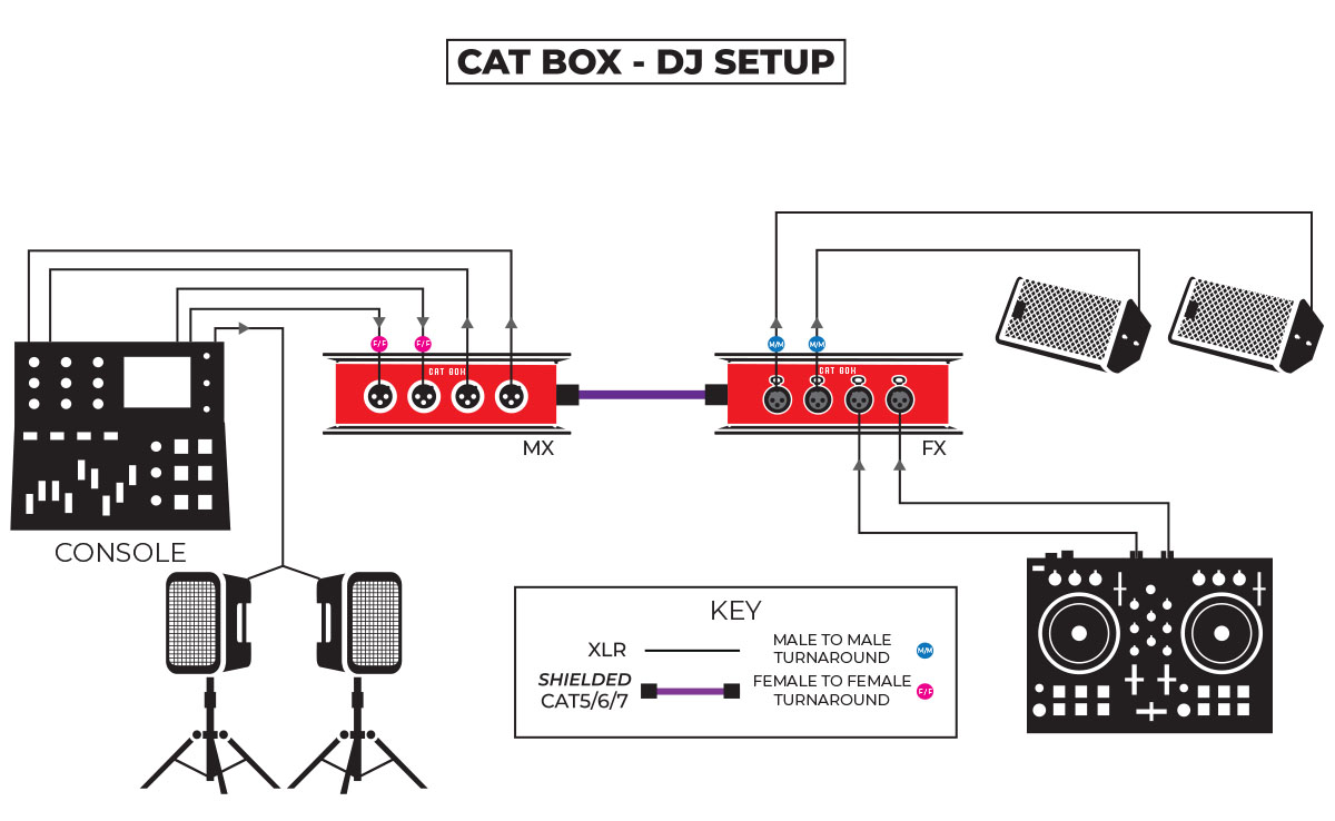
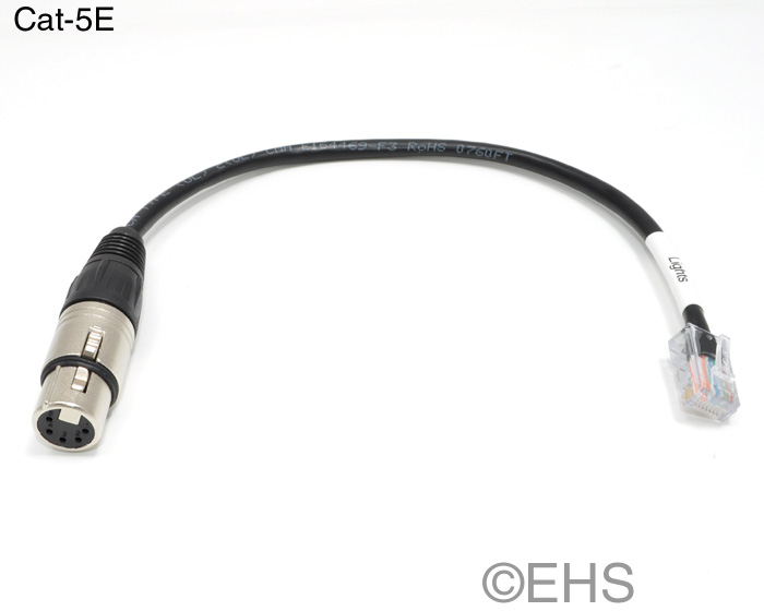
Cat5 to xlr wiring diagram. Xlr connectors from gls were around 150 each i used a total of 12 for the snake about 1800 total then add an ethercon connector to each box for 1150 each or 2300 and you have a total of around 6500 for a complete snake. It reveals the elements of the circuit as simplified forms as well as the power and signal connections in between the gadgets. Xlr connectors from gls were around 150 each i used a total of 12 for the snake about 1800 total then add an ethercon connector to each box for 1150 each or 2300 and you have a total of around 6500 for a complete snake. 3 pin xlr wiring standard. A wiring diagram is a simplified traditional photographic depiction of an electrical circuit. The above diagram shows you the pin numbering for both male and female xlr connectors from the front and the rear view.
Cat56 cable is made to minimise interference in the frequency range that is used by network protocols ie. Just make sure it is shielded. In our estimation the 568b connection is used in over 99 of all straight through applications. That range starts above the audio frequencies and extends to the 3 figure mhz range depending on the speed of the network link. It is the 568b diagram that we demonstrate in this tutorial and the 568a wiring is shown in the diagrams below mainly for illustration. This of course does not include the cat 5 cable itself.
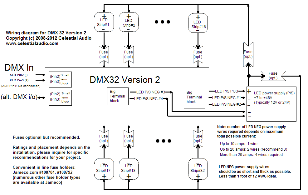
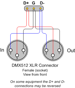
Below are the steps. It shows the components of the circuit as streamlined forms and also the power as well as signal connections between the tools. The rear view is the end you solder from here are the connections on each pin. A wiring diagram is a simplified conventional pictorial depiction of an electrical circuit. Connect the positive negative and ground wires from each xlr connector to the terminal adapter according to the diagram shown. However long you want it.
3 pin xlr connectors are standard amongst line level and mic level audio applications. How to make a cat 5 or cat 6 patch cable. The following picture shows the wiring diagram of the two standards. Look for cat 5 cat 6 wiring diagram with color code cable how to wire ethernet rj45 and the defference between each type of cabling crossover straight through. When you are doing the straight through wiring the cable pinout on the two ends of the cat5e cable should be the same. 5 pin xlr wiring standard.
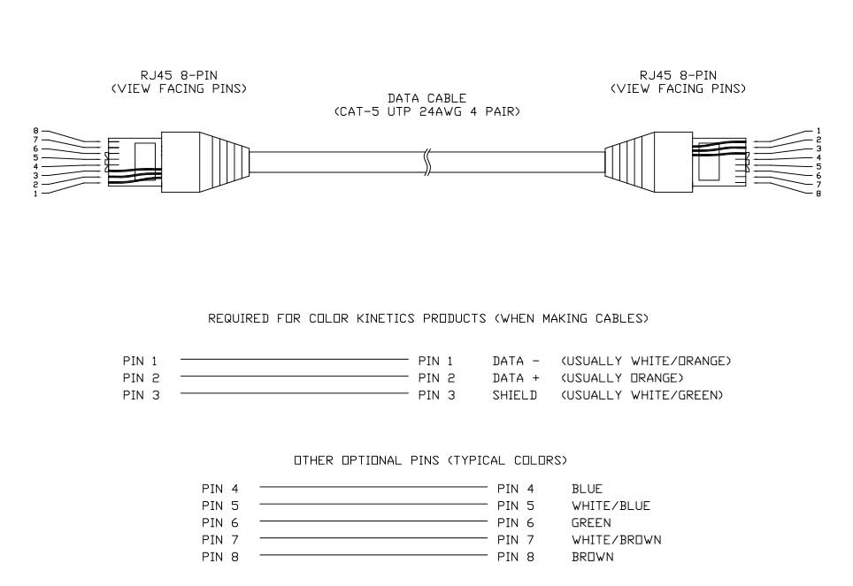
Variety of cat 5e wiring diagram wall jack. In the diagram below i show a possible wiring diagram that also takes into consideration the split pair wiring that a properly built rj45 ethernet cable needs to follow. Here is the dmx pin out. However for the crossover wiring method the rj45 pinouts on each end of the cat5e are different.
