A wiring diagram is a simplified conventional pictorial depiction of an electrical circuit. Download wiring diagram cat5 to dmx free files.

Chalice Wiring Indd Manualzz
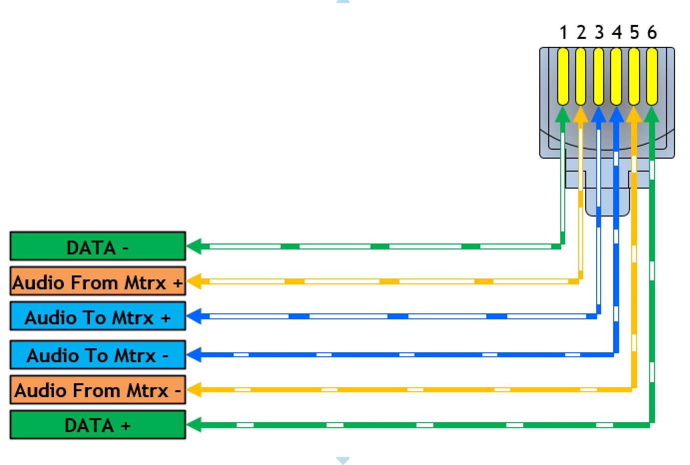
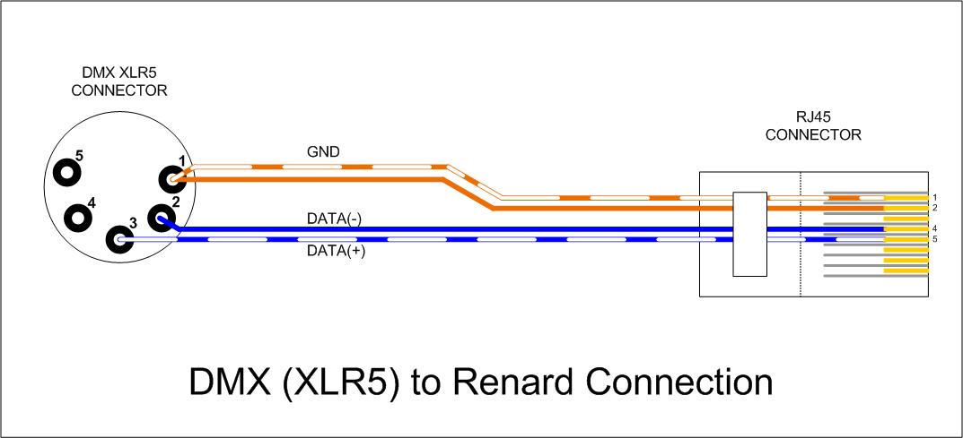
Cat5 to dmx wiring diagram. The following picture shows the wiring diagram of the two standards. Download wiring diagram cat5 to dmx pdf. Dave pretzlaff from our field service department walks you through how to do a proper termination of a cat5 cable for use with dmx in an etc installation. When you are doing the straight through wiring the cable pinout on the two ends of the cat5e cable should be the same. However for the crossover wiring method the rj45 pinouts on each end of the cat5e are different. Variety of cat 5 wiring diagram pdf.
Male rj45 connectors are especially prone to breakage over repeated re connections. Rj45 connectors may be used with cat5 cable for permanent wiring. It shows the components of the circuit as streamlined forms and also the power as well as signal connections between the tools. These are easy to find and allow you to run 1 4 universes over a single ethernet cable. Its generally acceptable to run dmx over cat5 or cat6 cable for up to. Variety of cat 5e wiring diagram wall jack.
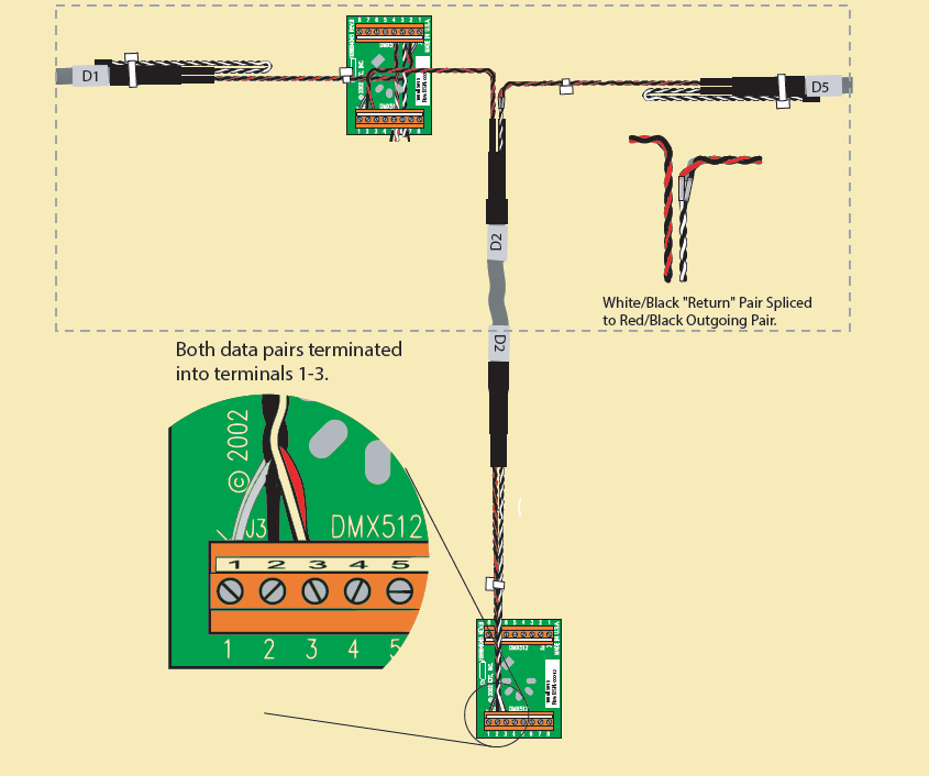
However etc supports dmx over cat5 with maximum total wire length per run of 500m1640ft. It reveals the elements of the circuit as simplified forms as well as the power and signal connections in between the gadgets. Wire must be belden 9829 9842 cat 5 or equivalent. A wiring diagram is a simplified traditional photographic depiction of an electrical circuit. The simplest way to run our dmx over ethernet is to literally use an adapter. Cat5 utp cable may be used inside metal conduit.
The connection of dmx equipment to non dmx equipment such as ethernet switches or telephone equipment may result in serious equipment damage andor personal injury as pins 4 and 5 may carry voltages of up to 48vdc or greater. Cat5 or equivalent is not preferred as a portable cable since it is not as rugged as other dmx cables. An adapter may be required when using a non philips color kinetics controller with data enabler. Dmx version only ethernet or dmx input power and data power input output to fixtures kinet is the standard ethernet lighting protocol from philips color kinetics. If youre looking to wire this up yourself heres an excellent resource for all the technical info. The last dmx device on the line must be terminated with a termination switch or resistor with a value of 100 to 120 ohms between pins 2 and 3.
Category wire is not recommended for loose or temporary cabling.


