Capacitor startrun wiring 06172012 433 pm. Wiring diagram single phase motors.

Single Phase Induction Motors Ac Motors Electronics Textbook
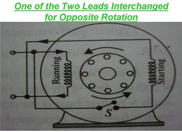
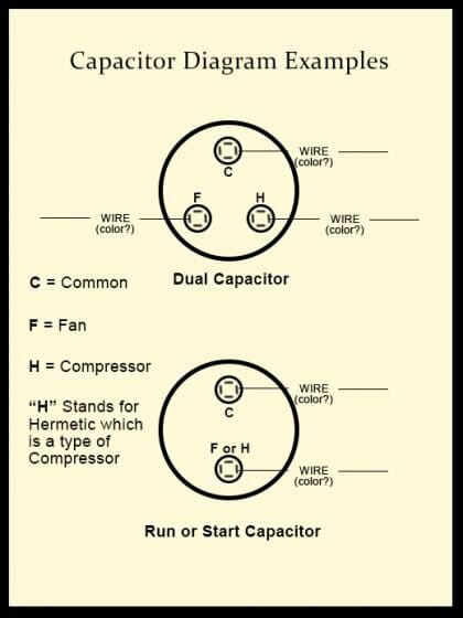
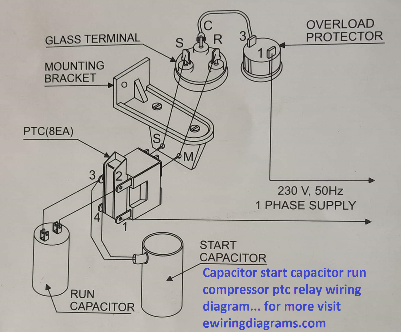
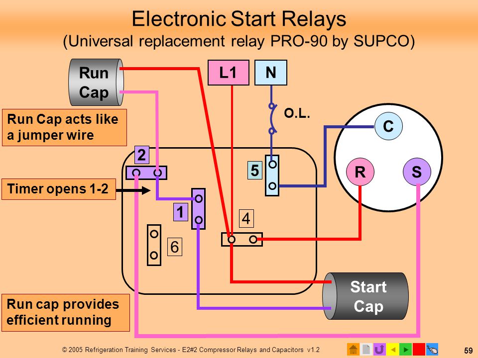
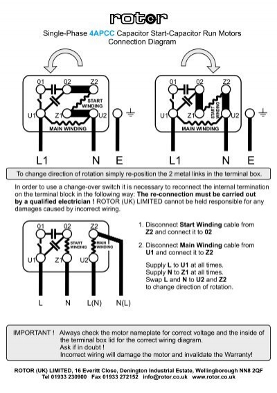
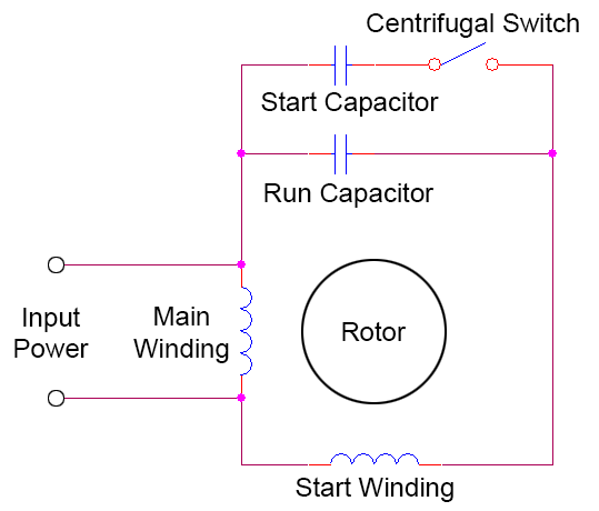
Cap start cap run wiring diagram. If your motor has an internal switch it is a capacitor start motor and the capacitor is wired in series with the switch iemain line in to one side of cap other side of cap to the switch. Push the wire terminal on the start capacitors second wire onto the run capacitors common terminal often labeled c com the wire connected to the motors run terminal marked as r on the motors wiring chart and the wire going to the hot terminal on the load side of the contactor also connects to this run capacitor terminal. The electrical schematic diagram on the right shows an illustration of a capacitor start motor. If not the structure will not work as it should be. 1empcc capacitor start capacitor run motors electric motors limited when a change of direction of rotation is required and a change over switch is to be used it will be necessary to reconnect the termination on the terminal block. See first diagram above.
Motor run capacitor wiring diagram ac motor run capacitor wiring diagram capacitor start capacitor run motor wiring diagram pdf capacitor start induction run motor wiring diagram every electric structure is composed of various diverse pieces. This picture cap start cap run wiring diagram single phase capacitor start in capacitor start run motor wiring diagram previously mentioned will be branded using. Posted by tops stars team in september 13 2013. Each component should be placed and connected with other parts in particular manner. Wiring diagram not just offers in depth illustrations of whatever you can do but additionally the processes you should stick to although carrying out so. I think this it the wiring diagram but i do not know what wire is what wire.
The reconnection must be carried out by qualified electrician. With such an illustrative manual you are going to be able to troubleshoot avoid and full your assignments without difficulty. L1 and l2 are designated as the two connection points representing the two electricity flow path inherent with single phase circuits where a single phase supply voltage is fed to the motors internal circuit. Capacitor diagram motor. Can you label what t1t4 t5 t17 and t18 would be on this. Single phase capacitor start capacitor run motor wiring diagram single phase motor wiring diagram with capacitor.
I do not have a centrifugal switch it is electrical. Motor run capacitor wiring diagram you will want a comprehensive professional and easy to comprehend wiring diagram.
