The db9 is also known as 9 pin d sub de 9 its correct name db 9 serial connector rs232 connector or null modem connector. R1 and r2 or the end of line resistors connect the two sides together.

Toyota Sienna Service Manual Short To B In Can Bus Line
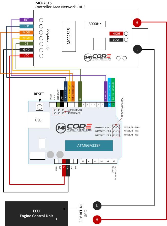
Can bus wiring diagram. Controller area network can is a serial network technology that was originally designed for the automotive industry especially for european cars but has also become a popular bus in industrial automation as well as other applications. Specifically an ecu can prepare and broadcast information eg. The broadcasted data is accepted by all other ecus on the can network and each ecu can then check the data and decide whether to receive or ignore it. Can is a multi master broadcast serial bus standard for connecting electronic control units ecus. For the remainder of this presentation and shop modules we will concentrate on the can b network as used in w203 w220. The can bus is primarily used in embedded systems and as its name implies is a network technology that provides fast communication among microcontrollers.
Can high low the can wiring consist of 2 wires called can high can h and can low can l. Notice that the can bus has two wires green and yellow. Sensor data via the can bus consisting of two wires can low and can high. The can bus is a balanced differential 2 wire interface running over either a shielded twisted pair stp un shielded twisted pair utp or ribbon cable. The can bus may be used in vehicles to connect engine control unit and transmission or on a different bus to connect the door locks climate control seat control etc. It covers wiring for the common db9 plug and socket often used with can bus test equipment.
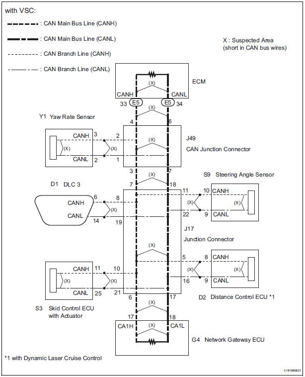
The power supply wiring can be either totally separate from the can bus lines using suitable gauge wiring for each module resulting in two 2 wire cables being utilized for the network or it can be integrated into the same cable as the can bus lines resulting in a single 4 wire cable. This article covers the basics of can bus wiring showing a simple can bus wiring diagram and how to wire up a can bus cable. The can standard was devised to fill this need. Can bus cabling is available from multiple vendors. The controller area network can specification defines the data link layer iso 11898 defines the physical layer. All the control modules are connected in a parallel circuit using either z splices or plug connector blocks x30.
This means that it is a high speed system. The diagram of the can bus system looks like this.


