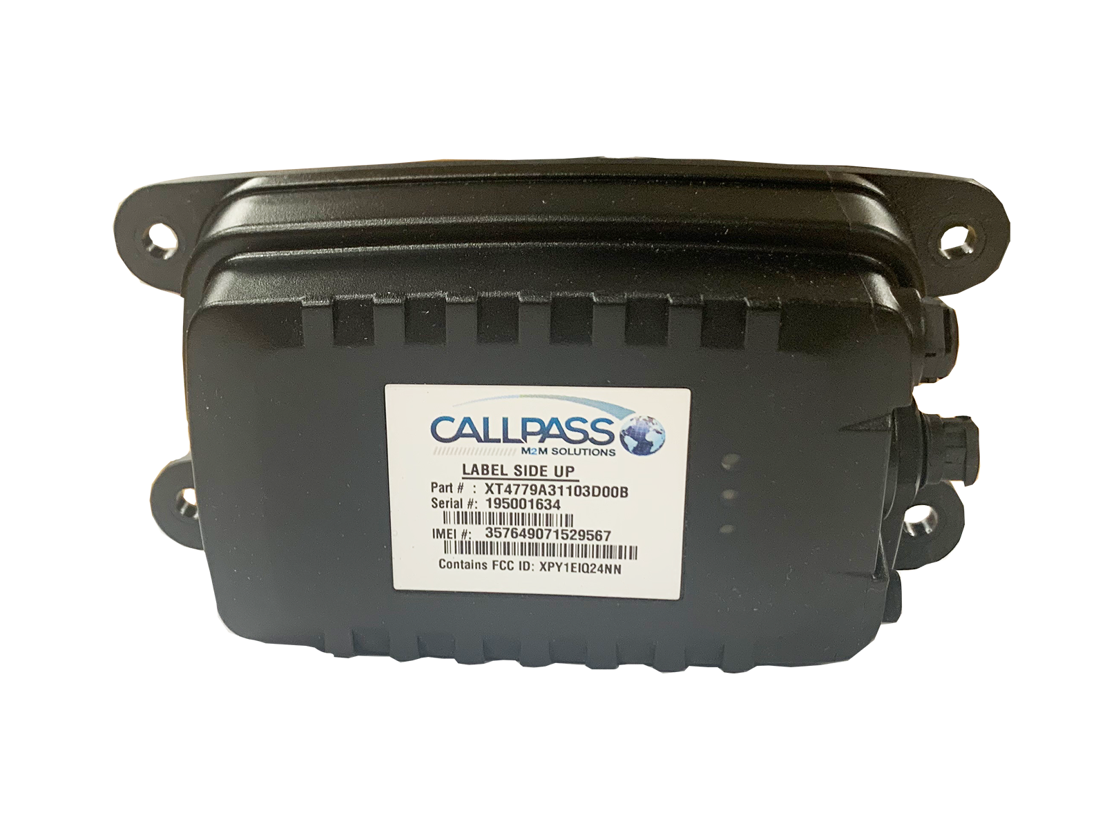
Now simply plug the 14 pin connect power cable into the device. It can withstand any job site and is designed to prevent theft of your mobile equipment including generators forklifts and more.
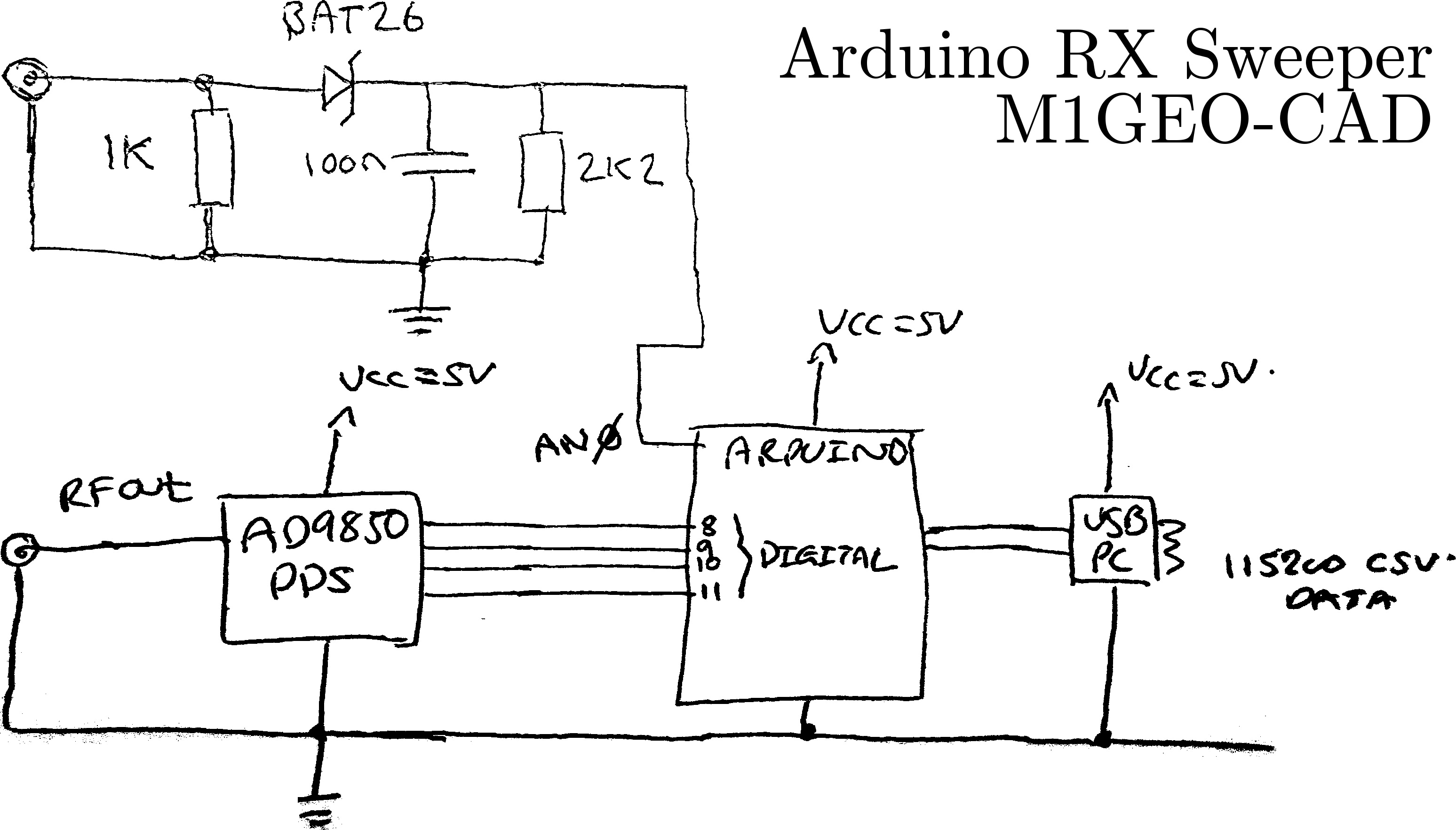
Arduino Dds Radio Receiver Filter Sweep George Smart M1geo
Callpass wiring diagram. Then connect the black wire to ground. Login to the callpass applications. Exclusive buy here pay here tracking device. Connect the white pin 7 wire from the devices power cable to the vehicles ignition wire that only has power at key on and crank. Combined with our proprietary lana equipment tracking software youll be able to make the most of your assets every day. When acquired the blue led will.
Contact callpass tech support for further testing instructions. Now that power is connected the green led is solid. A4006l terminal and jumper block. Watch product video features. Wiring diagrams can be helpful in many ways including illustrated wire colors showing where different elements of your project go using electrical symbols and showing what wire goes where. E 114 3 l 101 or ls 201.
Designed to provide buy here pay here and used car dealers anytimeanywhere access to their entire inventory directly from the igotcha gps app. Keep your diagram nearby. Black wire connects to the green wire on device connector 86 85 87. The ue led begins blinking while searching for the gps signal. This is why a good diagram is important for wiring your home accurately and according to electrical codes. Callpass tech cpt2016 6 below is a table of what each role can access on the website.
Superior gps tracking for the deep subprime auto finance industry never chase a delinquency again locate and recover with igotcha gps. Admin callpass view dealer admin dealer agent power user main alerts access access access access access companies access access reports access access access access live devices live devices access access access access access. Of the dash connect the red wire to a 6 24 v constant from the power cable. A gps tracker for equipment from callpass is easy to install compact and extremely durable. Do not follow this link or you will be banned from the site. Use this drawing when replacing old style e 104 units screw terminals with new style e 104 1 units which have wire leads.
Wires 87a and 30 of the relay connect to each side of the starter.


