The 16 channel relay module is a full height module that provides 16 relay outputs. Bently nevada 3500 wiring diagram keywords.

Pdf 3500 15 Ac And Dc Power Supplies Operation And
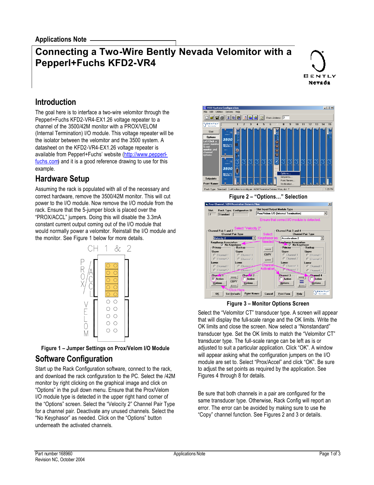
Bently nevada 3500 wiring diagram. Consult bently nevada applications note considerations when using eddy current proximity probes for overspeed protection applications when considering this transducer system for tachometer or overspeed measurements. Bently nevada 3500 vibration monitoring system. The rim must be located in slot 1 of. Any number of 16 channel relay modules can be placed in any of the slots to the right of the rack interface module. Bently nevada accelerometer wiring diagram awesome car p pl smoke. 3500 field wiring diagram package part number 130432 01 diagrams that show how to hook up a particular transducer.
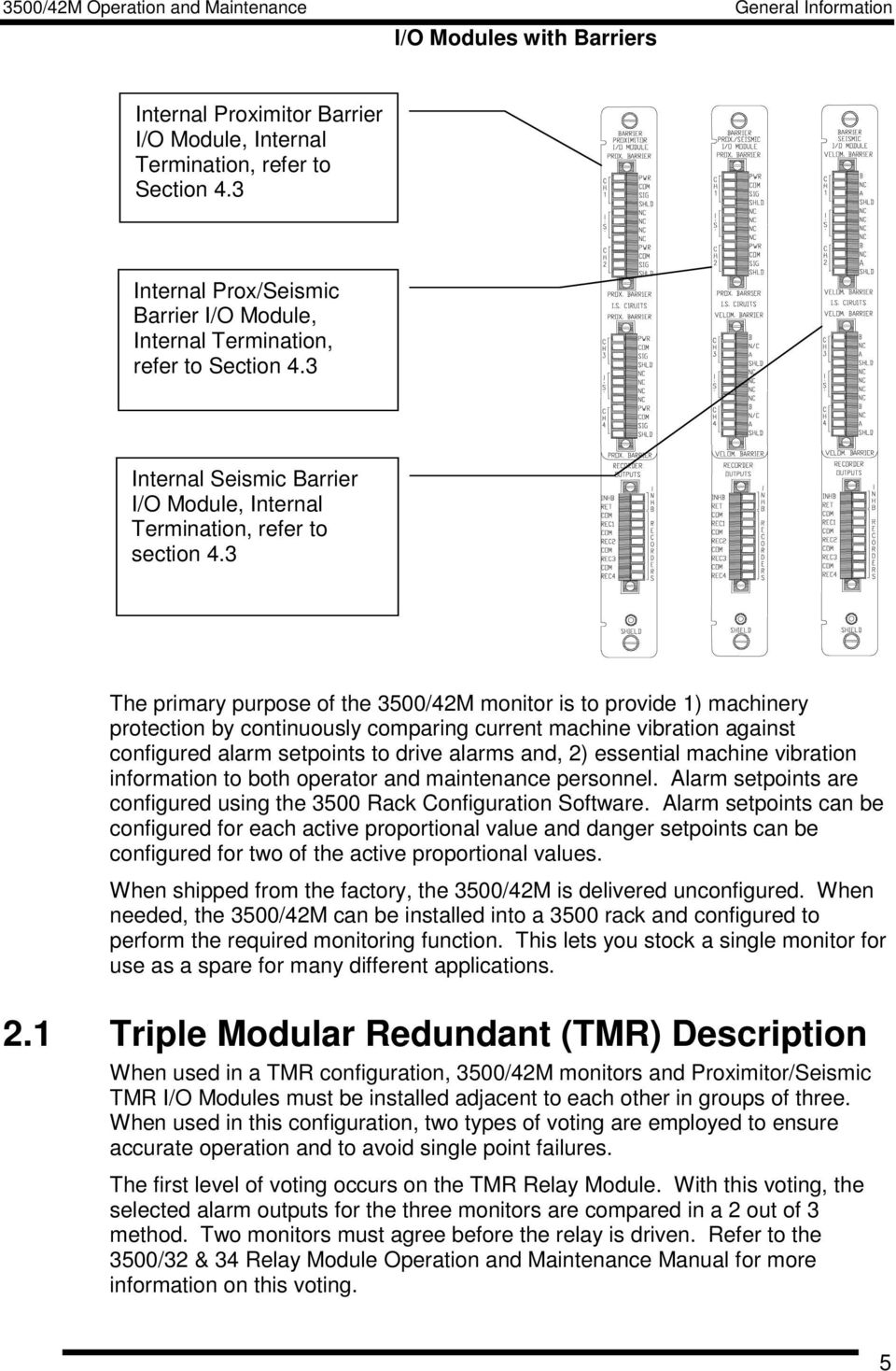
3500 system product datasheet bently nevada asset condition monitoring. Bently nevada 3500 wiring diagram created date. Bently nevadas 350042m proximitorseismic monitor offers four programmable channels for the 3500 system accepting input from proximitors and seismic transducers. Collection of bently nevada accelerometer wiring diagram. Bently nevada accelerometer wiring diagram sample bently nevada accelerometer wiring diagram awesome car p pl smoke. Bently nevada asset condition monitoring 350033 16 channel relay module.
The 350042m then conditions the signal to provide various vibration and position measurements and compares the conditioned signals with user programmable alarms. It supports a bently nevada proprietary protocol used to configure the rack and retrieve machinery information. Ght 200060 controlst license key ordering flow diagram. Each output of the 16 channel. Partnumber141526 01 revg0515 page2of2 document number documentdescription 143490 350044maeroderivativegtvibrationmonitormodule 135545 350045positionmonitor. The bently nevada bn 3500 vibration monitoring system the latest vibration system from bently nevada provides continuous online vibration monitoring suitable for machinery protection applications.
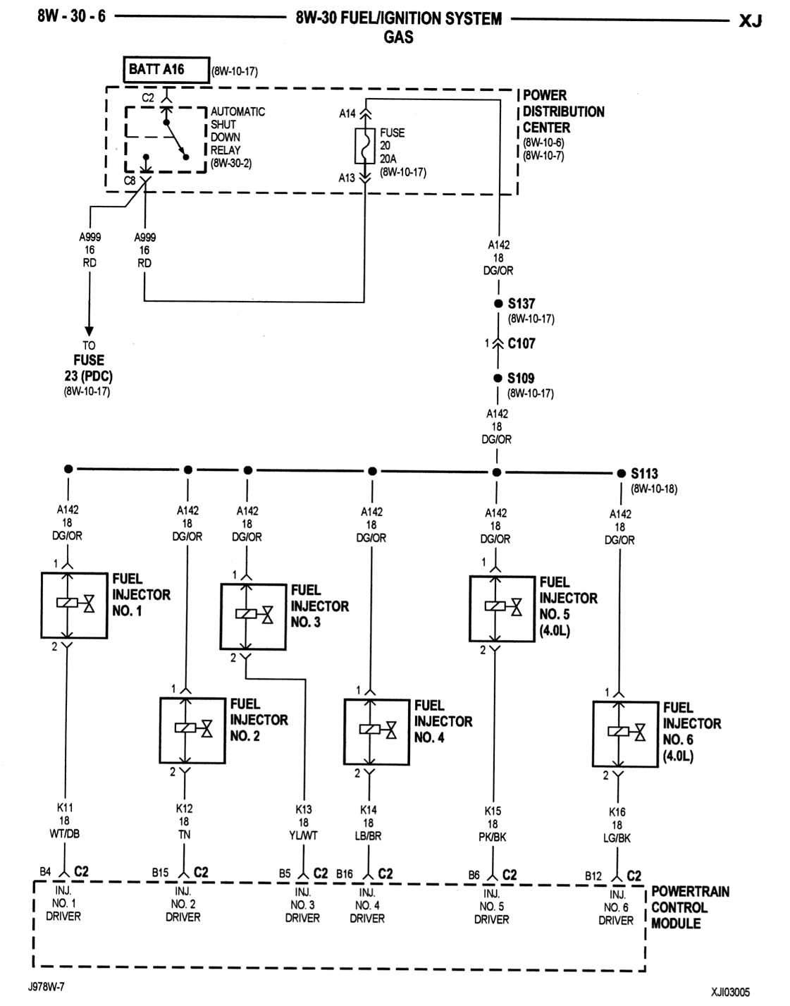
3300 xl 8 mm components are both electrically and physically interchangeable with non xl 3300 5 mm and 8 mm components. The rack interface module rim is the primary interface into the 3500 rack. It shows the components of the circuit as streamlined shapes and the power and also signal connections between the tools. Bently nevada accelerometer wiring diagram awesome car p pl smoke. A wiring diagram is a streamlined traditional pictorial depiction of an electrical circuit. Transducer input signals are buffered and sent to front panel bnc connectors for all monitors except the 350060 61 65 temperature and 62 process variable monitors.

